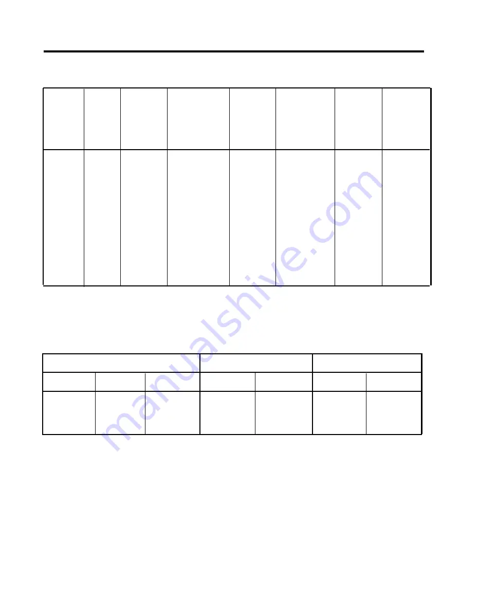
TABLE 2-3 4-Pair Wiring
Signal
Pair
Modjk
Pins
Modular
Cord
Wire
Colors
102A
103A
Z601A
Term
Stmp
DIW
Cable
Colors
25-
Pair
CabIe
Colors
25-Pair
Corn.
Pin
No.
V1T
V1R
CT
CR
-48V
GND
V2T
V2R
1
2
3
4
5
4
1
2
3
6
7
8
GREEN
RED
BLUE
ORANGE
BLACK
YELLOW
BROWN
SLATE
1
2
3
4
5
6
7
8
W-B
BLUE
W-O
ORANGE
W-G
W-BR
BROWN
W-B
B-W
W-O
O-W
W-G
G-W
W-BR
BR-W
1
2 6
2
2 7
3
28
4
2 9
TABLE 2-4 CO Line Wiring, 6-Position Jack, Single-Pair
RJ11 NI Specification
D2R Cord
CU Line Jack
Signal
Pin
Color
Plug
Plug
Pin
Signal
T
4
GREEN
4
3
3
T
R
3
RED
3
4
4
R
2-46 Wiring the System
Summary of Contents for administration and
Page 40: ...FIGURE 1 9 System architecture Theory of Operation 1 37 ...
Page 175: ...Top cover Front cover FIGURE 2 27 Control unit covers Testing the System 2 107 ...
Page 211: ...FIGURE 3 I A MERLIN II System Display Console The Administrator Attendant Console 3 3 ...
Page 213: ... FIGURE 3 2 A BIS 34D Console The Administrator Attendant Console 3 5 ...
Page 331: ...General Tests 4 55 Reaming the Control Unit 4 55 Testing Outside Lines 4 56 ...


