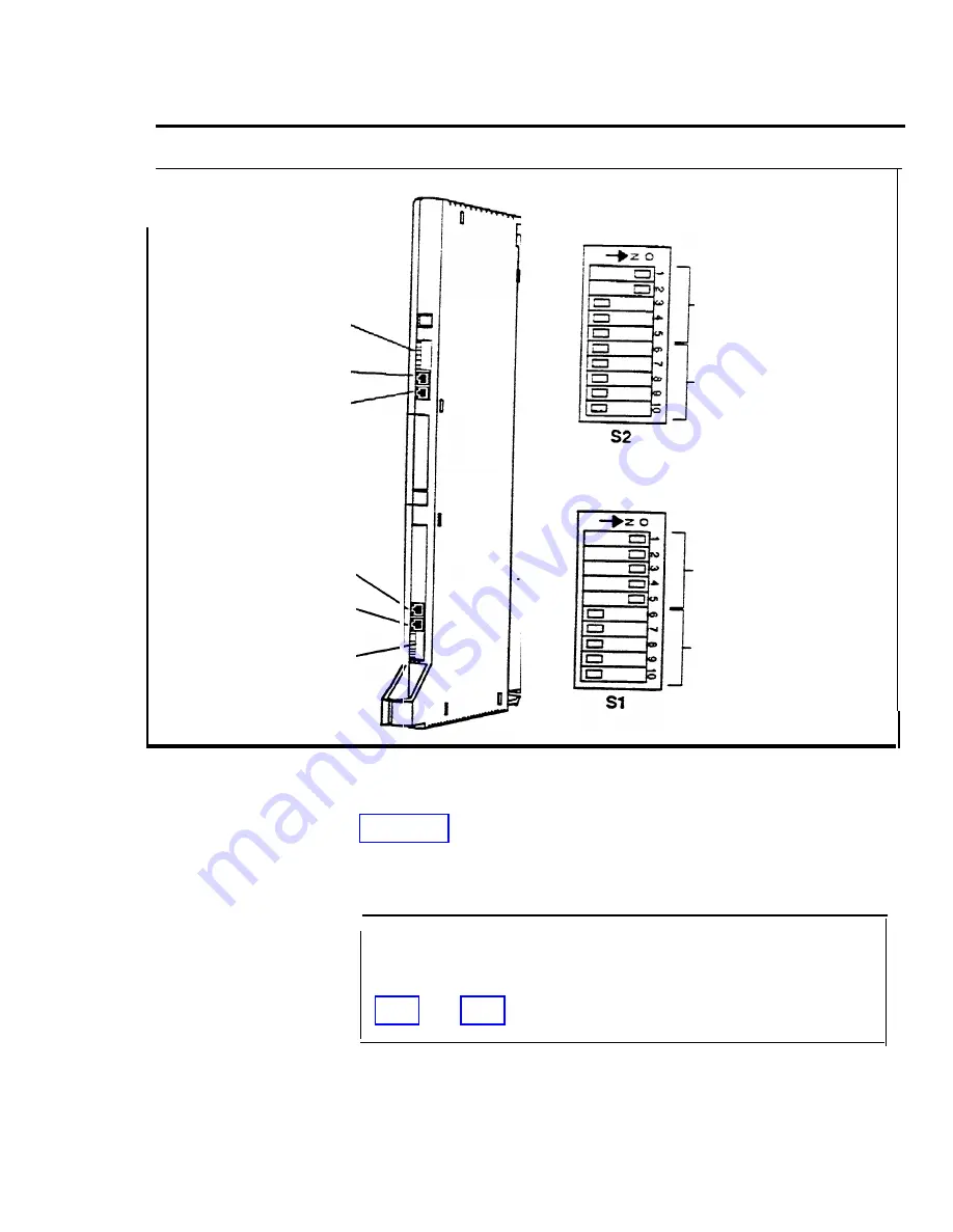
S2(controls
Ports 3 and 4)
Port 4
P o r t 3
Switches
1 through 5
control Port 4
(E&M
unprotected)
Switches
6 through
I
o
control Port 3
(E&M
protected)
Port 2
P o r t 1
S1 (controls
Ports 1 and 2)
Switches
1 through 5
control Port 2
(simplex)
Switches
6 through
1
0
control Port 1
(E&M
FIGURE 3-5 Setting tie line module DIP switches.
Table 3-2 shows the switch settings you should use to set
the signaling mode of each port to E&M protected, E&M
unprotected, or Simplex.
WARNING:
The protected mode must be used
whenever the E&M leads extend out-of-building and
are not connected to the network interface. See pages
Administering a New System
3-51
Summary of Contents for administration and
Page 40: ...FIGURE 1 9 System architecture Theory of Operation 1 37 ...
Page 175: ...Top cover Front cover FIGURE 2 27 Control unit covers Testing the System 2 107 ...
Page 211: ...FIGURE 3 I A MERLIN II System Display Console The Administrator Attendant Console 3 3 ...
Page 213: ... FIGURE 3 2 A BIS 34D Console The Administrator Attendant Console 3 5 ...
Page 331: ...General Tests 4 55 Reaming the Control Unit 4 55 Testing Outside Lines 4 56 ...


