WALL ATTACHMENT
The customer should have a backboard mounted at the
REQUIREMENTS
control unit site. If one is not in place, you may need to
attach a backboard to the wall. The backboard should
meet these specifications:
●
It should be made of 3/4-inch thick plywood.
●
It should be 4 feet wide by 2 feet high in order to
accommodate a basic control unit with an expansion
carrier and jack field. If ample wall space is available,
use a backboard that is 4 feet by 4 feet, regardless of
the system’s size. This size provides enough space for
future expansion.
●
It should be attached to the wall with hardware that has
a combined pull-out force of at least 500 pounds.
Determine the type of mounting surface on which the
board is to be mounted, and refer to Table 2-1 for
recommended hardware.
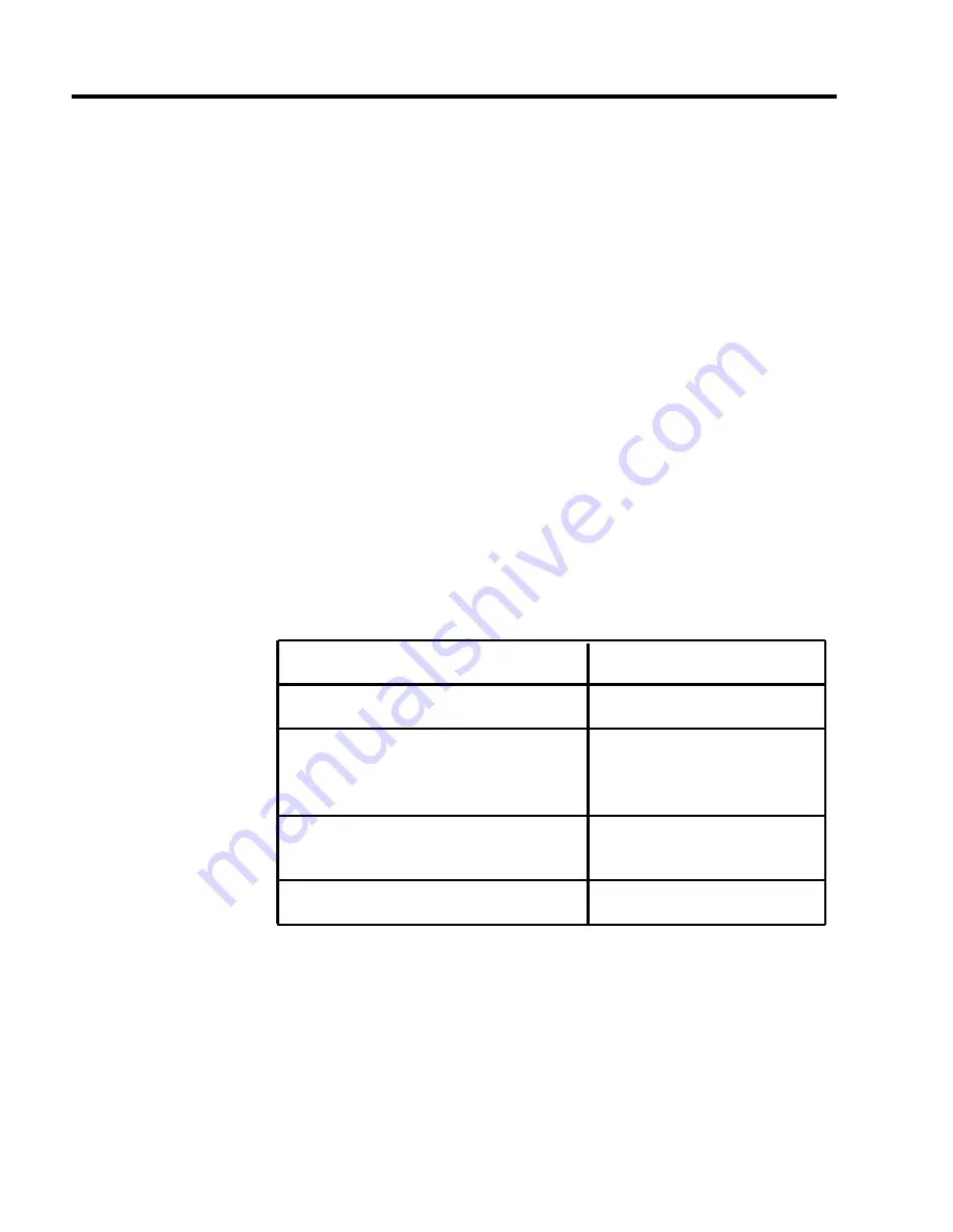
TABLE 2-1 Backboard Mounting Hardware
Mounting surface:
Hardware required:
Wood
Wood screws
Concrete
Brick
Masonry anchors
Cinder block
Plaster
Plasterboard
Toggle bolts
Sheet metal
Sheet metal screws
2-4 Preinstallation Requirements
Summary of Contents for administration and
Page 40: ...FIGURE 1 9 System architecture Theory of Operation 1 37 ...
Page 175: ...Top cover Front cover FIGURE 2 27 Control unit covers Testing the System 2 107 ...
Page 211: ...FIGURE 3 I A MERLIN II System Display Console The Administrator Attendant Console 3 3 ...
Page 213: ... FIGURE 3 2 A BIS 34D Console The Administrator Attendant Console 3 5 ...
Page 331: ...General Tests 4 55 Reaming the Control Unit 4 55 Testing Outside Lines 4 56 ...


