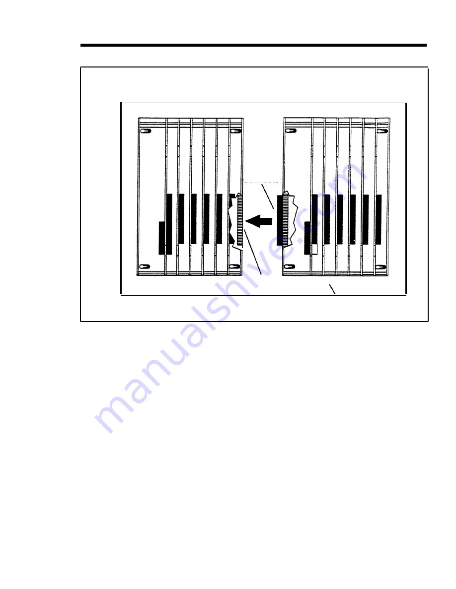
Mounting surface
Basic carrier
Expansion carrier
Connector
C a r d
e x t e n d e r
Backboard
FIGURE 2-13 Mounting an expansion carrier.
DETERMINING UNIT
LOAD
REQUIREMENTS
Review the following paragraphs that discuss unit load
requirements and module slot assignments before
installing modules.
A unit load is a measure of power used to determine the
eletrical load of the MERLIN II system. Due to variations
in system size and complexity, unit load computations
must be made to assure proper operation of the system
under all conditions.
The Power Supply Module provides 45 unit loads to each
carrier. A MERLIN II system with a basic and expansion
carrier can support 90 unit loads. If the unit load
requirement per carrier exceeds 45 unit loads, an Auxiliary
Power Unit is needed. This device connects to the Power
Installing the Control Unit 2-57
Summary of Contents for administration and
Page 40: ...FIGURE 1 9 System architecture Theory of Operation 1 37 ...
Page 175: ...Top cover Front cover FIGURE 2 27 Control unit covers Testing the System 2 107 ...
Page 211: ...FIGURE 3 I A MERLIN II System Display Console The Administrator Attendant Console 3 3 ...
Page 213: ... FIGURE 3 2 A BIS 34D Console The Administrator Attendant Console 3 5 ...
Page 331: ...General Tests 4 55 Reaming the Control Unit 4 55 Testing Outside Lines 4 56 ...


