MERLIN II
System
T
R
T 1
R1
M
E
Central
office
RJ2GX
T1
R1
T
R
E
M
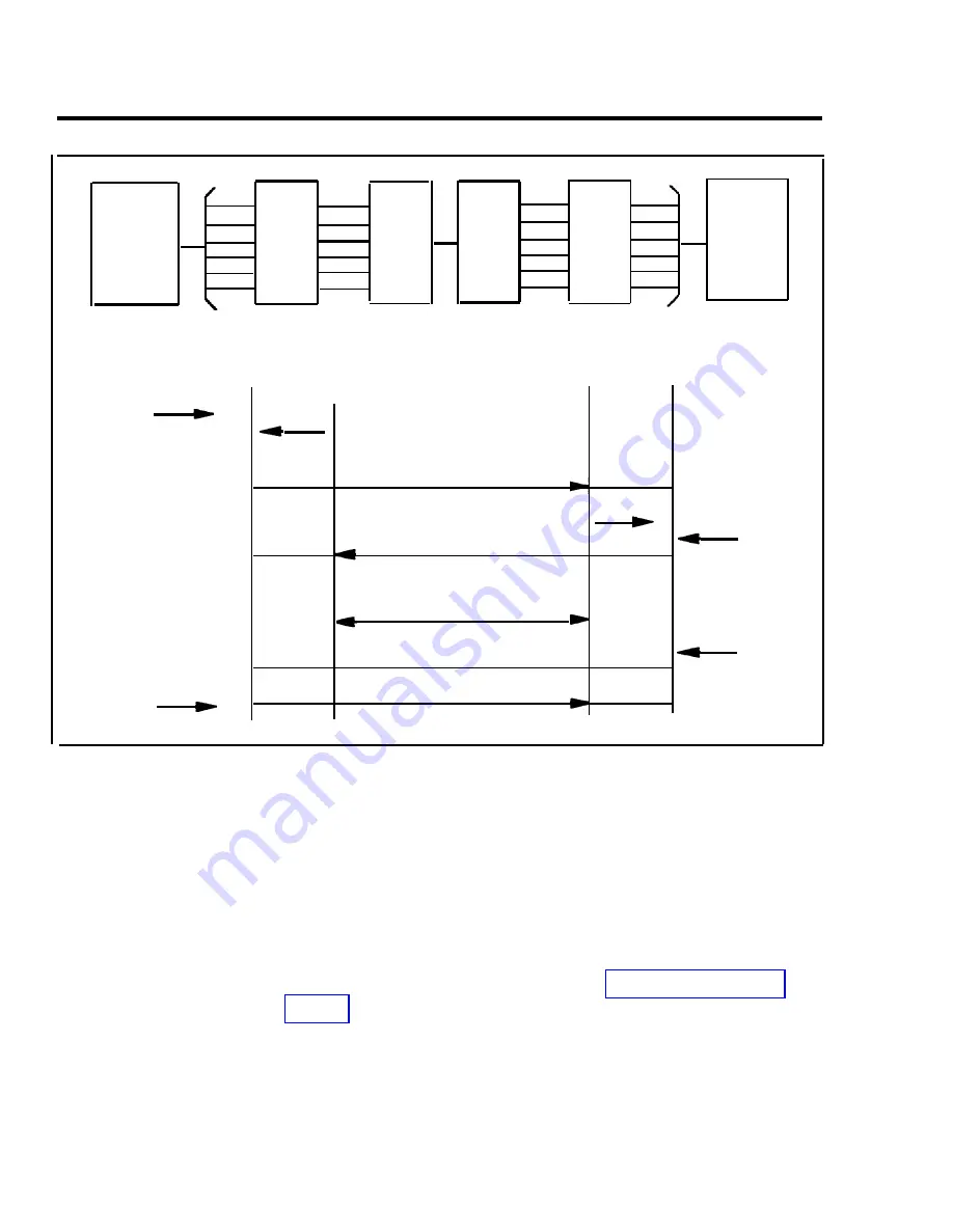
Off-hook
Site #1 dials
number for
site #2
E lead
On-hook
RJ2GX
Central
office
SITE #l
Dial tone
M lead
E lead
M lead
SITE #2
M lead of site #1 connected to
E lead of site #2
M lead of site #2 connected to
E lead of site #1
Conversation
Disconnect
Disconnect
E lead
Ring
M lead
M lead
E lead
Dimension
PBX
Off-hook
On-hook
FIGURE 1-11 E&M signaling.
E&M Tie Line
Parameters
The MERLIN II system 400EM Tie Line Module has four
line ports. Each must be administered individually. All tie
line options are software administered except for the
signaling format parameters (signaling mode and signaling
type). These are selected by DIP switches on the Tie Line
Module. The following is an explanation of tie line
options. For more information, see “Administering Tie
Lines” on page 3-50 in Section 3, “Administration”.
1-46 Theory of Operation
Summary of Contents for administration and
Page 40: ...FIGURE 1 9 System architecture Theory of Operation 1 37 ...
Page 175: ...Top cover Front cover FIGURE 2 27 Control unit covers Testing the System 2 107 ...
Page 211: ...FIGURE 3 I A MERLIN II System Display Console The Administrator Attendant Console 3 3 ...
Page 213: ... FIGURE 3 2 A BIS 34D Console The Administrator Attendant Console 3 5 ...
Page 331: ...General Tests 4 55 Reaming the Control Unit 4 55 Testing Outside Lines 4 56 ...


