background image

18 

Cellular service verification 

After  completing  the  setup  of  either  mode  of  the  cellular  connection,  it  is  important  to  determine  that  there  is  adequate 
signal strength before deciding on a final installed position. Cellular coverage can vary, even over a short distance, and a 
bad placement of the AT&T U115 can result in substandard or even non-existent cellular service. 

If the device is using an imbedded Cellular modem, the signal strength will be displayed on the front panel, right side. The 
color of the light labeled "CELL" will indicate the network connectivity as follows: 


Blue

 - LTE  


Green

 - non-LTE 4G / 3G (UMTS) 

If the device is using an external USB modem, y

ou can check the signal strength by pressing the “RESET” button on the 

back  while  powered  on  with  the  Cellular  USB  modem  inserted.  A  paper  clip  or  other  sharp  object  will  be  required  to 
properly depress this button.


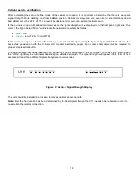
The signal strength will be represented by a sequence of LEDs illuminated on the front panel. Up to six LEDs, starting with 
the “online” light may be illuminated depending on detected strength. The signal strength will appear in this form for five 
seconds. At least three LEDs of signal strength are recommended. 


Figure 12: Cellular Signal Strength Display 


The unit should be installed in a location that gives optimal signal strength.  

Note:

 After the final location has been determined by the best signal strength the U115 needs to be rebooted in order to 

re-establish the cellular connection.


Summary of Contents for U115

Page 1: ...1 AT T U115 Install Guide Version D6 0 1 ...

Page 2: ...other AT T marks contained herein are trademarks of AT T Intellectual Property and or AT T affiliated companies All other marks contained herein are the property of their respective owners CALIFORNIA PROPOSITION 65 WARNING WARNING Cancer and Reproductive Harm www P65Warnings ca gov ...

Page 3: ...3 במוצר המוצר המוצר במוצר המוצר המוצר Class A היבואן אינטרנשיונל סרויסס נטוורק גלובל טי אנד טי איי 05107 לוד התעופה שדה קריית 4 הנגב רחוב naveeD DSA 60PFB 24 1 190250 Class A ...

Page 4: ...ivity 7 Configuring the U115 8 Access the U115 Web Interface 8 Primary IPv4 WAN Interface Setup 9 Configuring DHCP 11 Configuring a Static IP Address 12 Configuring PPPoE 13 Configuring an Always On Cellular Connection 14 Configuring a User Controllable Dial as Primary Configuration 16 Cellular service verification 18 Administrator Access 19 Establishing VPN Connectivity 20 LAN Port Configuration ...

Page 5: ...t connection will be provided by your ISP This type of connection includes DSL Cable and Managed Internet Connections It is also possible to connect to the Internet via high speed cellular access in which case you should proceed to the appropriate section in this guide Once an Internet Connection has been established the U115 will try to retrieve its configuration from the network and if successfu...

Page 6: ...uration of the primary interface through the U115 web interface in order to establish Internet access and to retrieve device configuration See Configuring a Static IP Address or Configuring PPPoE later in the guide Option b Cellular Connection Certain U115 s will have an imbedded cell card and SIM already installed If the device has an imbedded call card and SIM please work with your AT T account ...

Page 7: ...ion Services IS Department for assistance before proceeding If your computer is configured to use DHCP but the U115 is not providing your computer with an IP address please contact your IS Department In this case you will not be able to access the web Interface as described below Note After the AT T has retrieved its configuration the IP addresses given out on the LAN ports are likely to change fr...

Page 8: ...port The web interface can be used to access various administration functions and can allow the VPN connection to be controlled 1 Open your web browser 2 In the Address or Location box enter http attvpngateway att com and press the Enter key 3 This will take you to one of several possible initial pages depending on your configuration and connectivity options Common navigation icons appear on the u...

Page 9: ...nge DHCP settings follow these steps 1 Access the web interface as described on page 8 2 Click on the Control Panel navigation icon 3 Click the entry for Network Settings to display the Network Settings sub menu and click the entry for WAN IPv4 Settings as shown in Figure 3 Figure 3 Network Settings Selection ...

Page 10: ...d An Always On Internet Connection means that the connection will normally always be available and the U115 will try to re establish connectivity if the connection is lost The other type is for where an Internet connection is only established when required This is commonly used where having a connection up always may be expensive and there are periods of time when the connection is not required Co...

Page 11: ...he DHCP set up window 2 Select the DHCP options required by your ISP on Figure 5 Most ISPs do NOT require any of these values to be set 3 Press OK to save the new settings 4 At the end of the setup you will be asked to reboot to pick up the new configuration After reboot skip to the section titled Establishing VPN Connectivity on page 20 Figure 5 DHCP Settings ...

Page 12: ...o proceed to the Static IP set up window 2 Enter the Static IP information requested on Figure 6 and press OK to save the new settings The Static IP information is provided by your ISP 3 At the end of the setup you will be asked to reboot to pick up the new configuration After reboot skip to the section titled Establishing VPN Connectivity on page 20 Figure 6 Static IP Settings ...

Page 13: ... Figure 4 on and click OK to proceed to the to the PPPoE set up window 2 Enter the information requested on Figure 7 and press OK to save the new settings 3 At the end of the setup you will be asked to reboot to pick up the new configuration After reboot skip to the section titled Establishing VPN Connectivity on page 20 Figure 7 PPPoE Settings ...

Page 14: ...ame and AT Strings are optional fields that you can enter information into if they are required If these fields are not required then leave them blank Click NEXT to proceed to the next page 5 Enter the phone number provided by your Cellular service provider on Figure 9 6 Enter the user ID and password provided by your Cellular service provider Some networks APNs don t use the user ID and some Cell...

Page 15: ...15 Figure 8 Cellular Always On Settings Modem Properties Figure 9 Cellular Always On Settings Login Information ...

Page 16: ...Name and AT Strings are optional fields that you can enter information into if they are required If these fields are not required then leave them blank Click NEXT to proceed to the next page 5 Enter the phone number provided by your Cellular service provider on Figure 11 6 Enter the user ID and password provided by your Cellular service provider Some networks APNs don t use the user ID and some Ce...

Page 17: ...17 Figure 10 Cellular Dial as Primary Settings Modem Properties Figure 11 Cellular Dial as Primary Settings Login Information ...

Page 18: ...s using an external USB modem you can check the signal strength by pressing the RESET button on the back while powered on with the Cellular USB modem inserted A paper clip or other sharp object will be required to properly depress this button The signal strength will be represented by a sequence of LEDs illuminated on the front panel Up to six LEDs starting with the online light may be illuminated...

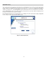
Page 19: ...e U115 Select Administrator enter the password provided by your IS Department and click OK Selecting General User and then clicking OK restricts the current session to be view only Certain functionality such as the ability to terminate the VPN connection is disabled If an Administrator password is not required Figure 13 is not displayed The U115 must be able to retrieve configuration from the netw...

Page 20: ...ge for an AT T Managed connection where the VPN Service connection method and Dial Backup VPN Service connection method are configurable by the user 2 One or more VPN connections may have been defined Each VPN connection will be represented in a status box on the left side of the page showing the current state of each connection If there is more than one VPN connection defined only the first VPN c...

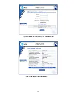
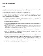
Page 21: ...21 Figure 14 Example of Login Page for AT T Managed Figure 15 Example of Connected Page ...

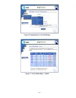
Page 22: ...rk Settings sub menu and click the entry for Local LAN Settings as shown in Figure 16 4 The next window will display the Local LAN Settings If VLANs have been configured the display will appear as in Figure 17 If VLANs have not been configured the display will appear as in Figure 19 If no VLANs have been configured skip to the description for Hub Mode on page 25 5 The display shows several rows so...

Page 23: ...23 Figure 16 Navigation to Local LAN Settings Figure 17 Local LAN Settings VLANS ...

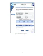
Page 24: ...24 Figure 18 VLAN DHCP Configuration ...

Page 25: ...ort information display as shown in Figure 19 In this case Local LAN equipment can be plugged into any available port on the back of the U115 If you see this page and you think that VLANs SHOULD have been configured please contact your IS department When complete return to Establishing VPN Connectivity on page 20 Figure 19 Local LAN Settings Ports Version D6 0 1 2018 AT T Inc All Rights Reserved ...

Reviews: