9
SCA2
P r e a m p l i f i e r
Table B - RIAA Board Gain Stage Link Setting
Mid point gain stage set LOW (11dB)
Link Z1 to
Z2
First gain stage settings.
Gain Setting
Gain mV
Gain dB
Link Position
High
1.14mV
59dB
Link both Y-Y and X-X
High/mid
1.6mV
55dB
Link Y-Y only
Mid
3.3mV
49dB
Link X-X only
Low
33.0mV
30dB
No links
Mid point gain stage set HIGH (24dB)
Link Z2 to
Z3
First gain stage settings.
Gain Setting
Gain mV
Gain dB
Link Position
High
0.25mV
71dB
Link both Y-Y and X-X
High/mid
0.38mV
68dB
Link Y-Y only
Mid
0.78mV
62dB
Link X-X only
Low
7.5mV
42dB
No links
Gain:
Gain is set by fitting the Z link in one of two positions (Z1 to Z2 or Z2 to Z3)
and by setting a combination of X and Y links. These links should be fitted according
to the desired input sensitivities specified in Table B.
Capacitive Load:
Capacitive load is set by selecting a link for the appropriate
capacitance value as illustrated in Diagram 3. Multiple links may be be used, in which
case the load value is the sum of the selected values. For example, links in the 470pF
position and 1000pF position give a total load value of 1470pF.
Resistive Load:
Resistive load is set by selecting a link for the appropriate capacitance
value as illustrated in Diagram 3. If no link is selected the default resistive load is 47
kilohms - appropriate for the majority of moving-magnet cartridges. A link in the -50
position will reduce any selected load by 50 ohms. For example,
links in the 200 position and -50 position give a total load
value of 150 .
Cartridge suppliers and manufacturers will be able to provide
details of the loading and gain settings appropriate to their
products. On some occasions there will be no specific
recommendation for the capacitive load on moving-coil
cartridges. In these cases it is best to assume no capacitance
need be selected (no links used).
The rear panel ground terminal should be used to connect
the pick-up arm earth lead.
2 . 3 O u t p u t s
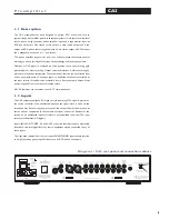
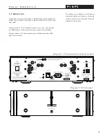
The SCA2 rear panel, illustrated in Diagram 1, carries
sockets for balanced main left and right output, unbalanced
main left and right output, and two unbalanced tape record
outputs.
Choice between the balanced and unbalanced main outputs
will depend on the input capabilities of the following power
amplifier (or active speakers). Use the balanced
option in preference if both options are possible.
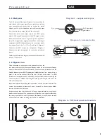
Connections to the primary output XLR sockets
follow the convention of pin 1 to ground, pin 2 to
signal “hot” and pin 3 to signal return (signal
ground). When connecting to equipment with XLR
(balanced) inputs the connectors should be wired
pin for pin (ie. 1 to 1, 2 to 2 and 3 to 3). Diagram 4
illustrates the XLR output pin arrangement and
Diagram 5 the connection scheme for a balanced
XLR - XLR cable.
The unbalanced main left and right outputs and the
tape record outputs should be connected using
good quality RCA phono terminated leads. Use of
the front panel volume, mute, or gain functions
does not effect the tape record signal.
Cables up to 50 metres in length may be connected
to the main outputs. Tape record cables should be
limited to 10 metres.
Pin 2, Signal (hot)
Pin 1, ground
Pin 3, Signal (return)
Diagram 4 - balanced output socket pins
Diagram 5 - balanced cable pin connections
To Power Amp or
Monitor Input
To Preamp Output


