10
SCA2
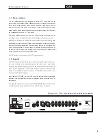
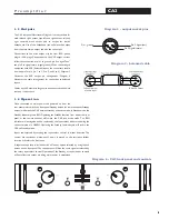
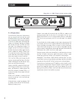
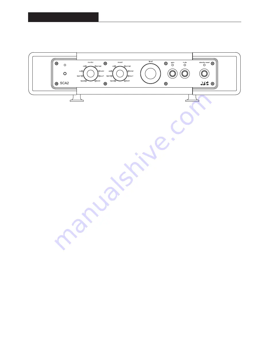
Diagram 6 - SCA2 front panel and controls
2 . 4 O p e r a t i o n
Once connected to mains power and powered-up
from the rear panel mains switch, the front panel
Standby Reset
button (or remote handset Standby
button) will switch the SCA2 between standby and
active modes. In standby mode the Standby Reset
indicator will illuminate. Operating the Standby
Reset function will switch the SCA2 into active
mute mode. The Standby Reset indicator will
extinguish and the Mute indicator will illuminate.
The
Mute
function automatically engages when the
SCA2 is switched from standby to active mode.
This precautionary feature provides an opportunity
for the volume and input settings to be checked
before audio is passed to the power amplifiers.
If all is well, the SCA2 may be brought into full
operation by pressing the Mute function. The Mute
indicator will extinguish. The Mute function can be
used at any time to silence the system.
Inputs are selected by rotating the
Monitor
select
control. The green indicator next to each monitor
option will illuminate to indicate selection. The
control has continuous movement. When it is
moved to the last input, further rotation will select
the first input.
Volume level is adjusted by rotating the
Level
control. A red indicator on the control indicates
the level selected.
Volume level can be reduced immediately by 12dB
by operating the
Gain
function. The Gain indicator
illuminates to indicate its use.
Optimum sound quality will be achieved when the SCA2 has reached normal
operating temperature and for this reason it is recommended that it be left in
standby mode when not in use. It is a wise precaution however to switch-off the
SCA2 from the rear panel power switch if it is to be left unused for an extended
period.
The
Record
select control selects the input source routed to the tape outputs. The
green indicator next to each record option will illuminate to indicate selection. The
control has continuous movement. When it is moved to the last input, further
rotation will select the first input. The source selected is made available at the tape
output sockets and is fully buffered to prevent signal interaction. The Level, Gain and
Mute functions have no effect on the record output signals.
Tape copying can be performed by selecting Tape 1 on the Record control to copy
from Tape 1 to Tape 2. In this case no signal will be routed to the Tape 1 output
sockets. Copying from Tape 2 to Tape 1 can be achieved in a similar manner.
Selecting Tape 1 on the Monitor control while also recording to Tape 1 (i.e. tape 1
is also selected on the record control) enables the off-tape signal from a three head
tape machine to be monitored. The Tape 2 circuit works in an identical manner.
Due to the nature of the electronics in ATC amplifiers it is quite normal for a sound
to be heard from the speaker when the power is applied or disconnected. The noise
heard will not damage the speaker and is quite normal. Although ATC uses the
highest-grade components, a different noise may be heard from each speaker due to
slight tolerance variations in the amplifier components.
P r e a m p l i f i e r

