4
4
CA2
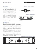
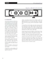
Diagram 2 - RIAA Phono Board and Jumpers
Table A - RIAA Jumper Settings
J1
J2
J3
Pos A
Pos B J4
J5
J6
Jumper settings for 1 Volt Output
Sensitivity
J1 and J4
J2 and J5
J3 and J6
10.0mV
Removed
Fitted (100
Ω
)
Position A
6.7mV
Removed
Removed (47k
Ω
)
Position A
5.1mV
Removed
Fitted (100
Ω
)
Position B
3.4mV
Removed
Removed (47k
Ω
)
Position B
2.2mV
Fitted
Fitted (100 )
Position A
1.4mV
Fitted
Removed (47k
Ω
)
Position A
1.1mV
Fitted
Fitted (100
Ω
)
Position B
0.7mV
Fitted
Removed (47k
Ω
)
Position B
Pos A
Pos B
P r e a m p l i f i e r
The phono amplifier can be configured to
accommodate a wide selection of phono cartridge
types by setting combinations of the board
mounted jumpers (links). Access to the phono
stage is gained by removing the cover of the
preamplifier. Diagram 2 illustrates the position of
the jumpers on the board while Table A details the
cartridge matching options available.
Pulling them gently away from the board with a
small pair of pliers and replaced in the appropriate
positions as shown in the diagram moves links.
Unused links can be “parked” on the board by
setting them at right angles on unused pins.
Jumpers J2 and J5 set the input load for each
channel of the cartridge. With the jumper in place
the load is 100 ohms. With the jumpers removed
the load is 47k
ohms.
Jumpers J3, J6, J1 and J4 set the gain (sensitivity) of
the phono input. J3 and J6 have two positions A and
B. In position A the gain of the phono stage is
reduced, in position B the gain is increased. J1 and
J4 can have the jumper fitted or removed. When
fitted the gain of the circuit is increased. By setting
combinations of these 4 jumpers, a range of
s
ensitivities can be accommodated.
For example: for a cartridge with a low sensitivity
J3 and J6 would be set in position B while J1 and
J4 would both have their jumper fitted. Table
A illustrates t
he input sensitivity and load
characteristics available. The manufacturer of the
cartridge in use will be able to recommend the
appropriate settings.

