5
5
1 . 3 O u t p u t s
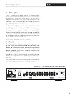
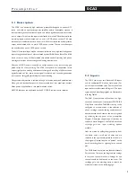
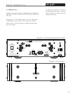
The CA2 rear panel illustrated in Diagram 1 carries sockets for
main left and right output, tape left and right output, left and
right summed mono output and an output for stereo
headphones. Use of the headphone jack will mute the output
from the main stereo output and also the sub output.
Connections to the main output may be from RCA phono
plugs or XLR plugs. Connections to the XLR output sockets
follow the convention of pin 1 to ground, pin 2 to signal “hot”
and pin 3 to signal return (signal ground). When connecting to
equipment with XLR (balanced) inputs, the connectors should
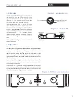
be wired pin for pin (i.e. 1 to 1, 2 to 2, and 3 to 3). Diagram 3
illustrates the XLR output pin arrangement. Diagram 4
illustrates the cable arrangement for connection to balanced
inputs.
Cables up to 50 metres in length may be connected to the main
stereo or sub outputs.
1 . 4 O p e r a t i o n
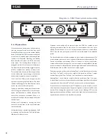
Once connected to mains power and powered up from the
rear panel mains switch, the front panel Standby button (or remote handset Standby
button) will switch the CA2 between standby and active mode. In Standby mode the
Standby Indicator glows RED. Operating the Standby function from either the front
panel or the remote handset will switch the CA2 into active mode. The RED
indicator will extinguish and be replaced by the Input select indicator showing the
current selection in GREEN. Operating the Standby function again will return the
CA2 to Standby mode.
Inputs are selected by rotating the input select control in either direction. The
control has continuous movement. When it is moved to the last input, further
rotation will select the first input.
A separate tape loop is included with a Monitor option selected by a single push
button on the front panel. The tape output will have the same signal as selected by
the rotary input select control. Operation of the Standby or tape monitor controls
will not affect this output providing mains power is maintained.
Diagram 6 - CA2 front panel and controls
CA2
P r e a m p l i f i e r
Diagram 3 - output socket pins
Pin 2, Signal (hot)
Pin 1, ground
Pin 3, Signal (return)
Diagram 4 - balanced cable
To Power Amp or
Monitor Input
To Preamp Output

