23 24
Ω
Ω
Ω
Ω
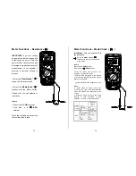
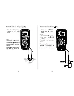
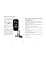
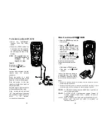
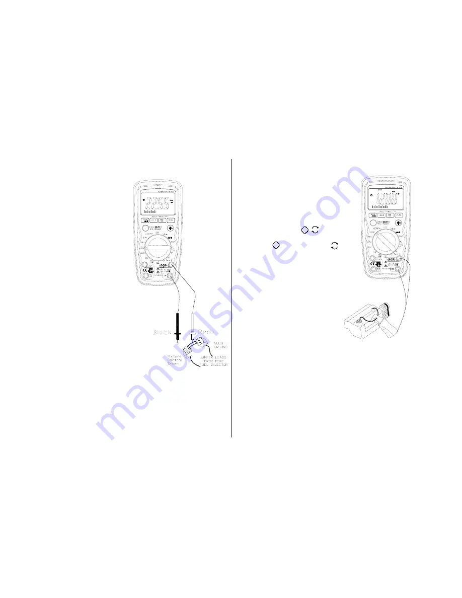
To measure pulse width (mS):
Select the
“mS-Pulse”
function with the rotary
switch .
Press the
±
TRIG button for
2 seconds until the negative
(-) trigger slope is displayed
on the upper left side of the
display.
NOTE : The applied time for
most fuel injectors is
displayed on the
negative (-) slope.
Insert:
Black lead in
COM
jack.
Red lead in
V-
Ω
-RPM
jack.
Connect:
Jumper wires between the fuel
injector and the harness
connector.
Black test probe to a good
ground at the fuel injector or the
negative (-) vehicle battery post.
Red test probe to the fuel
injector solenoid driver input on
the jumper cable.
Start the engine. A pulse width in
milliseconds should be read.
Note: Initially, the unit will read
“OL”, then readings will descend
and stabilize to the actual pulse
width. If “OL” remains,
re-check your connections.
Meter Functions-RPM/
×
10RPM
Select the
RPM
range with the
rotary switch.
OR
Select the
×
10RPM
range
with the rotary switch (1,000 to
12,000 RPM). Multiply the
displayed reading by ten to get
actual RPM.
Press STROKE / DIS
button to select through
RPM for 4-stroke, RPM
for 2-stroke and DIS ignitions.
Insert the inductive pickup
connecting terminals into the
meter.
Black lead in
COM
terminal.
Red lead in
V-
Ω
-RPM
terminal.
Connect the inductive pickup to
a spark plug wire. If no reading
is received, unhook the clamp,
turn it over and connect again.
Note:
Position the inductive pick-up as far away from the distributor and the
exhaust manifold as possible.
Position the inductive pick-up to within six inches of the spark plug or move
it to another plug wire if no reading or an erratic reading is received.
RPM 4
:
For RPM of 4-stroke engines which have 1 ignition on
every 4 engine strokes
RPM 2 :
For RPM of DIS ( Distributorless lgnition System) &
2-stroke engines which Have 1 ignition on every 2
engine strokes
PLEASE NOTE- THE RPM PICK-UP HAS AN ADJUSTABLE SENSITIVITY
SWITCH THAT CAN ALSO BE USED TO CORRECT AN
UNSTABLE READING.
4
2
4
2


