13
Chapter 3 Operation
3.1.3 “1/2”switch
“1/2” switch is at the front plate of the machine, on the right of “MIN/MAX” switch. Two
switches can be used at one time; you can choose different shelves of two switches according to
the metal material.
3.1.4 Overload light
If welding with large current for a long time and exceed the duty cycle, the overload lamp will
light (yellow), the machine will stop working until looking to the stated temperature. When the
overload lamp lights you must stop welding and wait about 15 minutes, you can continue.
3.2 Operation process
3.2.1 Use with cored wire
The welder can used with special
Φ
0.8 Flux wire that dose not require protective gas. This
wire, contrary to the case with electrodes, does not leave slag and gives better bread penetration
with substantially lower line absorption.
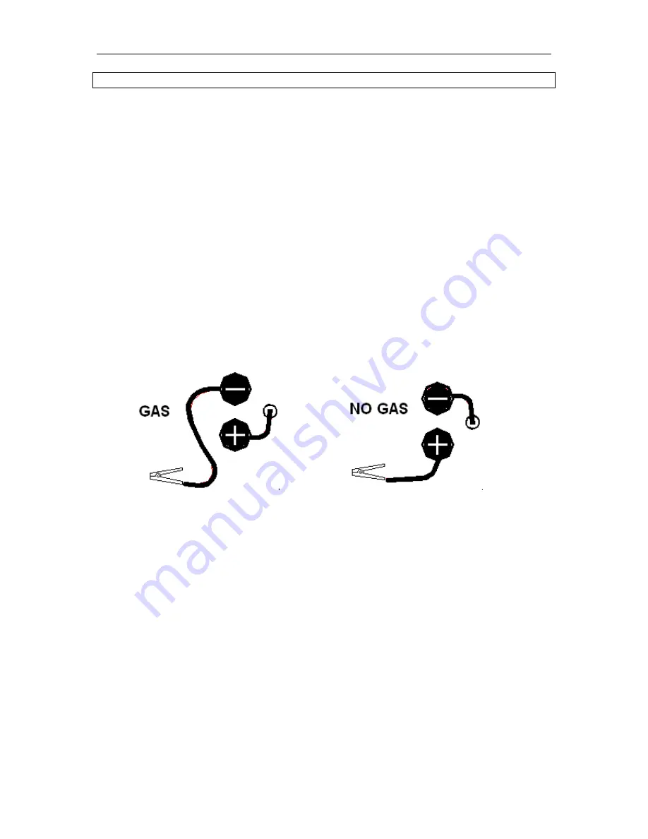
Make sure you use proper welding polarity: as diagram 3-2B., grounding cable connects “+”
terminal, another cable (welding torch cable) connect “-” terminal.
A B
Diagram 3-2
Step1: Use ground clamp to connect the grounding cable and work piece or connect the metal
carriages (as work table) make sure the clamp has been contacted fully with work piece and clear
the rust and paint.
Step2: Select the welding current, adjust the position of “MIN/MAX” and “1/2” switch, use higher
welding current for thicker material.
Step3: Check the position of power switch, position must be on “OFF”, then insert the inlet wire to
the socket (rated current of socket
≥
20A).
Step4: Discharge the nozzle cover and contact tip at the head of welding torch, pull the soft pipe.
Step5: The welding tongs that clamp the rod can’t be contacted with any grounding objects then
turn the
"ON/OFF “switch to “ON” position, the power lamp (green) will light.
Step 6: Press (and hold) the torch button until distance between wire and welding torch is 30mm
loosen torch button.
Step7: Close the power; fix the contact tip and nozzle cover onto the welding torch. (Wire must
through the contact tip and nozzle cover)


