background image

9

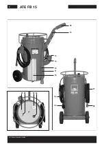
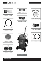
ATE FB 15 Operating Manual

Filling, bleeding the brake 
system, replacing mineral  
hydraulic oil

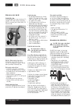
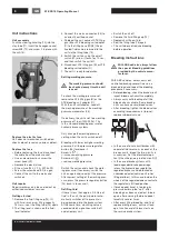
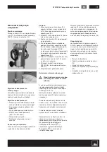
1.    Remove the fluid reservoir cap
2.    Extract the fluid completely from the 

fluid reservoir using the ATE suction 
bottle (A)

3.    Connect the ATE filling gun (B) to the 

filling hose (07/08); switch the unit on

4.    Completely fill the fluid reservoir with 

new fluid; disconnect the ATE filling 
gun (B)

5.    Fit the suitable ATE bleeding unit 

adapter (C) airtight to the fluid reservoir

6.    Connect the filling hose (07/08) to the 

ATE bleeding unit adapter (C)

7.    Insert the hose of the ATE collection 

bottle (D) onto a bleed valve; open the 
bleed valve until fresh, clear,  
bubble-free fluid flows out

8.    Repeat the procedure on each of the 

bleed valves with the collection bottle 
fitted

9.    When fitting a new tandem main  

cylinder: Press the brake pedal down 
as far as it will go several times while 
the fluid is flowing out in order to re-
move the air bubbles completely from 
the tandem main cylinder

10.  End of bleeding; switch the unit off; 

remove the filling hose (07/08) first, 
then the ATE bleeding unit adapter (C)

11.  Correct the fluid to the MAX mark  

using the ATE suction bottle (A)

12.  Check the bleeding hole of the origi-

nal fluid reservoir cap for permeability 
and then fit it

Special bleeding


Special bleeding is not permitted 
on vehicles with ABS

1.    Bleeding in special cases via bleed 

valve (from bottom to top). This meth-
od must be used when bleeding at 
more than 2 bar (200,000 Pa).

2.    Extract the fluid completely from the 

fluid reservoir using ATE suction bottle 
(A)

3.    Connect the ATE filling gun (B) to the 

filling hose (07/08); switch the unit on

4.    Fill the fluid reservoir up to the MAX 

mark; disconnect the ATE filling gun (B)

5.    Connect the ATE collecting bottle (D) 

to a bleed valve; open this bleed valve

6.    Press the brake pedal down as far 

as it will go and fix in place using the 
ATE pedal arrester (E)

7.    Connect the lever nipple of the auxil-

iary hose (F) to a further bleed valve 
of the same brake circuit; open this 
bleed valve

8.    Connect the filling hose (07/08) to the 

ATE auxiliary hose (F)

9.    Open every bleed valve in the brake 

circuit with the ATE collection bottle 
(D) connected until fresh, clear, bub-
ble-free fluid flows out

10.  End of bleeding; close bleed valve on 

the ATE auxiliary hose (F); switch the 
unit off; remove the filling hose (07/08) 
first, then the ATE auxiliary hose (F); 
bleed the second brake circuit accord-
ingly

11.  Remove the ATE pedal arrester (E)
12.  Correct the fluid in the fluid reservoir 

up to the MAX mark

Low-pressure leakage test

If a low-pressure leakage test is to be 
carried out, the unit remains connected 
to the fluid reservoir after the standard 
bleeding procedure.
•   With the unit switched on, pull the 

pressure regulator button (04) to re-
lease it, and screw out (

) as far as 

possible

•   Switch the unit off; allow the system  

to stand for 5 minutes

•   The pressure must not decrease  

during this period

•   If the pressure does decrease, check 

the brake system

Afterward, set the unit to 2 bar 
(200,000 Pa) again.

Filling and bleeding the  
clutch system

The hydraulic clutch system is bled via 
the master cylinder reservoir. If any prob-
lems with bleeding occur (on trucks and 
buses), bleeding can take place via the 
bleed valve of the slave cylinder using 
the ATE auxiliary hose (F). 

Disposal of mineral-oil- 
based fluids

These fluids must be collected separate-
ly in a suitable container and disposed of 
by an approved disposal company.


Mineral-oil-based fluids must not 
be mixed with other fluids, since 
they must otherwise be disposed 
of as expensive special waste.
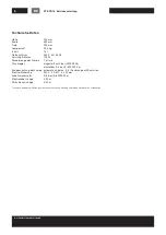
Technical data

Height 

745 mm

Width 

380 mm

Depth 

705 mm

Empty weight 

20.5 kg

Contents 

15 l

Power supply 

230 V  50–60 Hz

E-motor capacity 

125 W

Delivery rate of pump 

1.3 l/min 

Pressure regulator 

set to 2 bar (200,000 Pa)


adjustable 0–3 bar (0–300,000 Pa)

Final switch-off of the pump  automatically with 0.5 l residual fluid, with buzzing noise
Electric fuse 

230 V  2 A  MT  5 x 20 mm

Working pressure manometer 0–6 bar (0–600,000 Pa)
Electric cable length 

4.20 m

Filling hose length 

3.50 m

We expressly reserve the right to make technical modifications, including modifications to the design.

GB

Summary of Contents for FB 15

Page 1: ...Brakethrough Technology 03 9302 1660 4 740231 ATE FB 15 ...

Page 2: ...2 ATE FB 15 Continental Aftermarket GmbH 01 02 03 04 07 08 06 05 09 10 14 15 12 11 16 ...

Page 3: ...t entflammbaren Flüssigkeiten be treiben Bremsflüssigkeit auf glykolischer Basis führt zur Zerstörung des Gerätes Vor Wartung oder Reinigung darauf achten daß das Gerät ausgeschaltet und der Netzstecker 05 gezogen ist Bei einer eventuell erforderlichen Repa ratur einschließlich Ersatz der Netzzu lei tung ist das Gerät an den Fachhändler da der Einsatz von Spezialwerkzeug er forderlich ist einzusen...

Page 4: ...t bei Auslieferung auf 1 bar 100000 Pa eingestellt Dies ist normaler Entlüftungsdruck für hydrau lische Bremsanlagen Verändern des Arbeitsdrucks nur bei ausgeschaltetem Gerät Entlüften mit niedrigerem oder höherem Arbeitsdruck Druckreglerknopf 04 durch Ziehen entriegeln Hineindrehen Arbeitsdruck erhöhen Herausdrehen Arbeitsdruck reduzieren Gerät einschalten und Arbeitsdruck überprüfen Gegebenenfal...

Page 5: ...saugen 3 ATE Füllpistole B an Füllschlauch 07 08 kuppeln Gerät einschalten 4 Ausgleichsbehälter bis MAX Mar kierung füllen ATE Füllpistole B abkuppeln 5 ATE Auffangflasche D an ein Ent lüfterventil anschließen dieses Entlüf terventil öffnen 6 Bremspedal bis Anschlag betätigen und mit ATE Pedalfeststeller E fest stellen 7 Hebelnippel vom ATE Zusatzschlauch F an ein weiteres Entlüfterventil des glei...

Page 6: ...ördermenge der Pumpe 1 3 l min Druckregler eingestellt auf 2 bar 200000 Pa einstellbar 0 3 bar 0 300000 Pa Endabschaltung der Pumpe automatisch bei ca 0 5 l Restmenge mit Summton Elektro Sicherung 230 V 2 A MT 5 x 20 mm Arbeitsmanometer 0 6 bar 0 600000 Pa Elektrokabel Länge 4 20 m Füllschlauch Länge 3 50 m Technisch bedingte Änderungen auch Kontruktions Änderungen bleiben ausdrücklich vorbehalten...

Page 7: ...e with easily flammable fluids Glycol based brake fluid will lead to destruction of the unit Before maintenance or cleaning make sure that the unit is switched off and the mains connector 05 has been discon nected from the power supply If any repairs should become necessary including replacement of the mains sup ply power cable the unit must be sent to the specialist retailer it was purchased from...

Page 8: ... 04 to release it Screw in increase working pressure Screw out reduce working pressure Switch the unit on and check the work ing pressure If necessary switch the unit on again and re adjust the pressure After correct setting of the working pres sure press the pressure regulator button 04 back in to secure it Refilling fluid If there is less than approx 0 5 liters of fluid in the unit the pump moto...

Page 9: ...e brake circuit open this bleed valve 8 Connect the filling hose 07 08 to the ATE auxiliary hose F 9 Open every bleed valve in the brake circuit with the ATE collection bottle D connected until fresh clear bub ble free fluid flows out 10 End of bleeding close bleed valve on the ATE auxiliary hose F switch the unit off remove the filling hose 07 08 first then the ATE auxiliary hose F bleed the seco...

Page 10: ...łynami na bazie oleju mineralnego Nie używać z płynami palnymi Użycie płynów hamulcowych na bazie glikolu prowadzi do uszkodzenia urządzenia Przed konserwacją lub czyszczeniem uważać na to by urządzenie wyłączyć i wyciągnąć wtyczkę 05 Jeżeli wymagane są naprawy lub też wymiana elementów zasilania urządzenie należy odesłać do specjalistycznego serwisu ponieważ konieczne jest stoso wanie specjalnych...

Page 11: ...C 7 Urządzenie jest gotowe do pracy Ustawianie ciśnienia roboczego Przed każdym użyciem urządze nia należy sprawdzić ciśnienie robocze A celu sprawdzenia ustawionego ciśnie nia roboczego należy zdjąć pistolety napełniające ATE B lub króćce odpo wietrzające ATE C Odczytać ciśnienie robocze na mano metrze roboczym 03 przy włączonym urządzeniu Ciśnienie robocze przy dostawie usta wione jest na 1 bar ...

Page 12: ...ietrzają cy otwierać zawór odpowietrzający aż do wypłynięcia nowej czystej cie czy pozbawionej pęcherzyków 8 Po kolei powtórzyć tę procedurę na każdym zaworze odpowietrzającym przy podłączonej butelce zbiorczej 9 W przypadku montażu nowej tande mowej pompy głównej Podczas wypływu cieczy kilka razy powoli wcisnąć pedał hamulca do końca aby zupełnie usunąć pęcherzyki powietrza z tandemowej pompy głó...

Page 13: ...atkowego ATE F z zaworu odpowie trzającego siłownika sprzęgła Utylizacja cieczy na bazie olejów mineralnych Ciecze te należy odpowiednio zebrać do pojemników zbiorczych i utylizować za pośrednictwem autoryzowanej firmy zajmującej się gospodarką odpadami Ciecze na bazie olejów mine ralnych nie mogą być mieszane z innymi cieczami ponieważ te muszą być utylizowane jako drogie odpady specjalne ATE FB ...

Page 14: ...ermarket GmbH 03 9302 9053 3 740255 03 9302 9211 3 740266 03 9302 1660 4 740231 03 9302 9402 3 740269 03 9302 9022 2 740244 03 9302 9004 2 740239 03 9302 9070 3 740257 03 9302 9200 2 740264 5x20 mm M 2A 250V 03 9302 9250 1 740267 ...

Page 15: ... Conformity CE Description of Product Electrical Brake Bleeding Equipment Type ATE FB 15 The designated product is in conformity with the European Directive 2006 42 EG Full compliance with the standards listed below proves the conformity of the designated product with the provisions of the above mentioned EC Directive DIN EN 61000 6 2 200603 Ber 1 2011 06 DIN EN 61000 4 5 2007 06 DIN EN 61000 4 2 ...

Page 16: ...Marke des Continental Konzerns Continental Aftermarket GmbH Guerickestraße 7 60488 Frankfurt Deutschland Telefon 49 69 7603 1 Fax 49 69 761061 www ate de 91 9998 4216 4 09 19 02 2019 Continental Aftermarket GmbH ...

Reviews: