background image


ATEC

-PANDA 

Type 2188 
Type 2168 

54 cm Color TV Set 


Service Manual 

Summary of Contents for 2168

Page 1: ...ATEC PANDA Type 2188 Type 2168 54 cm Color TV Set Service Manual ...

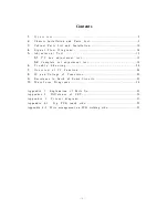
Page 2: ...m e n t t e s t 1 8 6 T r o u b l e S h o o t i n g 2 0 7 O v e r v i e w o f I C F u n c t i o n 2 4 8 I C a n d Vo l t a g e o f T r a n s i s t o r 2 9 9 R e s i s t an c e t o E a r t h o f S o me C i r cu it s 3 2 10 W a v e f o r m D i a g r a m s 3 4 A p p e n d i x 1 E x p l a n a t i o n o f P a r t s N o 3 5 A p p e n d i x 2 D i f f e r e n c e o f C RT 5 0 A p p e n d i x 3 C i r c u i...

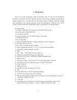
Page 3: ...ctions Remote Control 9 Easy release of all channels with a single key 10 Closed Caption Decoder with CC1 CC2 T1 and T2 decoder capabilities 11 Caption only on Mute optionally selectable 12 Mute 13 Half Mute 50 Volume pressinga single key 14 Without releasing MUTE Volume can be diminished 15 Smart Picture key SOFT STANDARD SHARP and PERSONAL 16 Quick View key 17 Time related features Alarm Timer O...

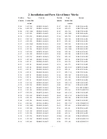
Page 4: ...71J NAARD R122 1 6W 1K RDB102J NAARD R226 1 6W 8 2K RDB822J NAARD R123 1 6W 1K RDB102J NAARD R314 1 6W 1K RDB102J NAARD R124 1 6W 1K RDB102J NAARD R331 1 6W 3 3K RDB332J NAARD R125 1 6W 1K RDB102J NAARD R345 1 6W 15K RDB153J NAARD R126 1 6W 1K RDB102J NAARD R346 1 6W 10K RDB103J5NBAND R127 1 6W 1K RDB102J NAARD R373 1 6W 22K RDB223J NAARD R128 1 6W 220 RDB221J NAARD R402 1 6W 3 3K RDB332J NAARD R1...

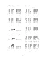
Page 5: ...DB330J2NBAND R640 1 4W 2 4K RDC242J NABRD RVD701 1 6W 1 5K RDB152J NAARD R641 1 6W 220 RDB221J5NBAND R2001 1 6W 10K RDB103J NAARD R642 1 6W 1K RDB102J NAARD R2002 1 6W 10K RDB103J NAARD R643 1 6W 10K RDB103J NAARD R2003 1 6W 8 2K RDB822J NAARD R644 1 6W 47K RDB473J NAARD R2004 1 6W 10K RDB103J NAARD R645 1 6W 470 RDB471J NAARD R3000 1 6W 100 RDB101J NAARD R651 1 6W 22K RDB223J NAARD R3001 1 6W 100...

Page 6: ...1 2W 15K RSF153J5ACDND C139 50V 15P CCF150J1CA FC R931 1 2W 2 2 RSD2R2J4ABBND C202 50V 0 01u CKF103Z1FA FC C204 50V 0 01u CKF103Z1FA FC C226 50V 0 01u CKF103Z1FA FC Wire resistor C301 50V 0 01u CKF103Z1FA FC R513 5W 3 9 RWH3R9K3AK NR C303 50V 8P CCF8R0D1CA FC R602 RX27 3A RWH1R8K5AF NR C304 50V 1000P CKF102K1BA FC 5W 1 8 C318 50V 0 01u CKF103Z1FA FC R603 5W 2 2K RWH222J5AQ NR C403 50V 1000P CKF102...

Page 7: ... 400V 220u CEM221M3AESNK C913 50V 100P CCF101J1CL NC C613 25V 100u CED101M1AMBNP C914 50V 470P CKF471K1BL NC C617 50V 33u CEF330M1ACAFP C923 50V 100P CCF101J1CL NC C622 25V 2200u CED222M2A MKNP C924 50V 470P CKF471K1BL NC C624 16V 470u CEC471M1ACCFP C941 2KV 2200P CKX222K2BL ND C626 25V 1000u CED102M1AMHNP C628 250V220u CEH221M2EMLNP Electrolytic C630 35V 330u CEE331M1AMFNP capacitor C632 16V 470u...

Page 8: ... 5mm LEE004 NJ C201 100V 0 022u CFG223K1 L NW FB625B 6 5 1 5mm LEE004 NJ C207 63V 0 1u CAY104K1 K FJ L502 M COIL LEA001 3 NJ C302 100V 0 01u CFG103J1 L NW LW545 M COIL LEA001 3 NJ C305 100V 0 01u CFG103J1 L NW C319 100V 4700P CFG472K1 L NW C401 63V 0 47u CAY474K1 L NJ Linearity filter C402 50V 0 22u CAY224K1 L NJ L601 Linearity filter LG 003 NL C407 100V 0 1u CFG104K1 L NW C409 100V 0 022u CFG223K...

Page 9: ...111 1N4148 T77 DR1N4148 RR VD704 1N4148 T77 DR1N4148 RR 1N4148 T77 DR1N4148 RH 1N4148 T77 DR1N4148 RH VD114 MTZJ5 1B DZMTZJ5R1B RR VD706 1N4148 T77 DR1N4148 RR HZ5C1 DZHZ5C1 RH 1N4148 T77 DR1N4148 RH VD2001 RGP10D DRRGP10D 01ND VD721 MTZJ7 5C DZMTZJ7R5C RR VD2002 MTZJ12A DZMTZJ12A RR HZ7C2 DZHZ7C2 RH HZ11C2 DZHZ11C2 RH VD809 MTZJ5 1B DZMTZJ5R1B RR VD401 RGP10D DRRGP10D 01ND HZ5C1 DZHZ5C1 RH VD501 ...

Page 10: ...1815 GNF XS151 TJC3 2A GACV2001 Y V701 2PC1815G Q2PC1815 GNF KP TJC3 5A GACV5001 Y V901 2SC2482 Q2SC2482 NN XS3101 TJC3 6A GACV6001 Y KSC2330 KQ TJC3 6A GACV6002 Y V911 2SC2482 Q2SC2482 NN KSC2330 V921 2SC2482 Q2SC2482 NN XS901 CRT Socket GBAVL007 A KSC2330 XS801 AV terminal GBBH2 02 Y IC VD110 CW574CS NCW574CS N TPAGC Test probe GABV1001 Y N103 HS0038B NHS0038B N V640 KA431Z NKA431Z F N602 KA7805...

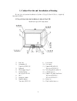
Page 11: ... 2188 Cuban cabinet 1 Front Case 2 Loudspeakers 2 Tap screws ST4X12 8 3 Trademark 4 Elastic engaged ring 2 5 Combined button Tap screws ST3X12 2 6 Lens 7 Transparent window 8 Optical conductor Tap screws ST3X12 2 9 Power switch 10 Press spring 11 Supported blocks M6 4 Tap screws ST4X20 12 12 Nuts with quincunx washer 4 13 combined nuts 4 14 Support of Fly Back Transformer Tap screws ST4X12 1 Tap s...

Page 12: ...ull out the chassis from the front cabinet Tube Remove Warning Don t move the deflecting coil and magnetic body on the neck of tube must carefully keep those parts in good condition except the CRT is damaged The CRT surface discharge should be made before disassembling 1 Remove chassis 2 Put the front cabinet with tube downward lay it down on a soft table board 3 Unscrew four combined nuts on ear ...

Page 13: ... 8 3 Trademark 4 Elastic engaged ring 2 5 Combined button Tap screws ST3X10 3 6 Guide light beam Tap screws ST3X10 2 7 Transparent window 8 Power switch 9 Press spring 10 Rubber gasket 4 11 Metal gasket 4 12 Combined nuts5X40 4 13 Rear cover 14 Support of high voltage package Tap screws ST4X12 1 Tap screws ST4X16 1 15 Hook of power cord 16 Mark label on rear cover ...

Page 14: ...pull out the Chassis from the front case CRT disassembly Warning Don t move the deflecting coil and magnetic body on the neck of tube must carefully keep those parts in good condition except the CRT is damaged The CRT surface discharge should be made before disassembling 1 Remove chassis 2 Put the front case with tube downward lay it down on a soft table board 3 Unscrew four combined nuts of ear r...

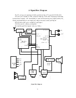
Page 15: ...ignal processing of horizontal vertical small signals TDA7056B is used for power amplifier of sound signal LA7840 is used for vertical power amplifier The detailed signal flow diagram is shown as follows Signal block diagram V IN EXT AUDIO IN RF AGC VEDIO OUT EXT V IN SELECT V OUT N201 LA76814 SECAM R Y IN SECAM B Y IN SDA SCL RGB_IN R G B OUT BAND1 BAND2 N101 CPU LA8632XXX SDA SCL R G B OUT H V T...

Page 16: ... SIGNAL 3 receive black signals produced inside of CPU TEST SIGNAL 4 receive pane and cross signals produced inside of CPU SOUND TRAP used for fine adjustment of sound trap frequency WOOFER for woofer control ON is available M1 MENU MENU 1 setting When enter MENU1 adjustment test menu CPU will automatically set Picture to status of Standard and close Picture enhancement setting Description LA76814...

Page 17: ... test When enter MENU5 adjustment test menu CPU will automatically set Picture enhancement to status of closed color saturation to 0 brightness to 50 CL Color saturation control BT Brightness control CT Contrast control SB Sub brightness RB GB BB Cutoff of red green blue gun RD GD BD Excite of red green blue gun M6 MENU MENU6 for setting of color decode item When enter MENU6 adjustment test menu C...

Page 18: ...matically set Picture to status of Standard and close Picture enhancement FM GAIN Sound frequency discrimination gain VIDEO LEVEL Video detection output level OSD CONSTANT OSD contrast SUB COLOR NTSC system sub color SUB COLOR PAL system sub color SUB SHARP Sub sharpness SUB TINT Sub tint RBI ABL TH Adjustment of ABL initial control position BRI ABL 1 ABL unable 0 ABL enable 5 1 3 Preset of I2 C b...

Page 19: ... SC 0 31 5 SUB CONT 0 127 127 OSD H display 0 63 20 SUB COLOR 0 127 127 NTSC SUB COLOR 0 127 127 PAL M4 RF AGC 0 63 20 SUB SHARP 0 63 63 SUB TINT 0 127 51 M6 R B Balance 0 15 7 BRI ABL TH 0 7 4 R B Angle 0 15 7 BRT ABL 0 1 0 5 2 Complete set adjustment test method 5 2 1 Set main power supply B Receive color bar signals and set Picture to Standard status Adjusting VR601 let B voltage 117 0 5 V 5 2 ...

Page 20: ...of FBT let the brightness of white level and gray level of picture conform to conventional requirement of adjustment of manufactory b Select option to SC and press V then adjust Screen potentiometer of FBT let a dim mono color one color of red green and blue sometimes may lean to yellow violet or white horizontal light line display on screen Remember this color press the numeric key 1 2 5 6 9 0 le...

Page 21: ... with conventional CPU standby some difficulties are occurred for failure estimation When the switching type power supply operating normally B 117 V but B 17 V when come into standby status T611 26V Rectifying and Detection H Dri Power Supply 117V Rectifying and Detection H OUT Power Supply 15V Rectifying and Detection Audio Power Amplifying 14V Rectifying and Detection 10V N603 12V Rectifying and...

Page 22: ... output Check voltage at pin of V501 C 19 V Check V505B pole and N201 PIN27 waveform Check V501 horizontal drive stage Check filament circuit of FBT CRT Check horizontal output stage and deflection circuit Check corresponding parts Check N201 PIN25 5V input current at this pin is 10 mA Check N201 Check voltage at N101 PIN16 0 V Check voltage at V602E V602C After restart TV check voltage of negativ...

Page 23: ...waveform existed at N201 PIN44 Check circuit between PIN 46 44 of N201 Check CVBS waveform at N201 PIN19 PIN20 PIN21 Check operating status of TUNER Check N201 Check CRT board Check 180 V power supply on CRT board Check bus between N101 N102 N201 Whenever open or interconnect on the bus from CPU to E2 PROM and main chip no picture can occur Check FBP waveform at N201 PIN28 Check external element c...

Page 24: ...T 5V Check 15V CPU 5V Supply Check V102 RESET circuit Check oscillating waveform at N101 PIN 10 PIN 11 Check functional inching key of the TV whether pressed Manual RESET Check crystal oscillator and external elements Check N101 Y Y Y Y Y Y N N 10V Y N N N N N When searching automatically channels observe whether can display picture Check BT voltage of TUNER 30 V Check SD voltage variation at CPU ...

Page 25: ...SYS IN2 32 No connected VDD 12 Connected to 5 V power supply SYS IN1 31 No connected KEY1 13 Keyed input 1 NC 30 No connected KEY2 14 Keyed input 2 NC 29 No connected AFT 15 AFT voltage input SCL 28 EEPROM SCL X RAY 16 X RAY protection input SDA 27 EEPROM SDA RESET 17 High level Reset NC 26 No connected FILT 18 Filtering OSD BLANK 25 OSD blanking output CATV 19 CVBS signals input B OUT 24 OSD B ou...

Page 26: ...n No 28 I2 C clock bus SCL0 port Pin No 29 SDA1 no used Pin No 30 SCL1 no used Pin No 31 NC Pin No 32 NC Pin No 33 Identification signal input Note If no signal at TV mode SD PIN33 is at low level after 10 seconds CPU will enter to status of standby In other conditions Video S Video this status cannot occur Pin No 34 Remote signal input Pin No 35 and 36 NC Pin No 37 NC Pin No 38 Blanking output as...

Page 27: ...ng GND X RAY 34 VCC VIF 8 Power supply intermedium frequency amplifying NC 35 No used FM FIL 9 Sound detection filtering APC FIL 36 Color APC filtering AFT OUT 10 AFT output ACC FIL 37 ACC filtering BUS DATA 11 Data bus XIAL 38 3 58MHz Crystal oscillator BUS CLOCK 12 Clock bus NC 39 No used ABL 13 ABL SELECT V OUT 40 Output of selection of internal external video R IN 14 Character red input GND V ...

Page 28: ...ion description Symbol PIN Function description GND 1 INV IN 5 Signal input V OUT 2 Vertical deflection output VCC2 6 Power supply input VCC2 3 Power supply of output stage PUMP UP 7 Pump power supply NON INV IN 4 Input 7 5 N601 MC44608P75 Function Controlled oscillator of switching type power supply Symbol PIN Function description Symbol PIN Function description Demag 1 Switching transformer dema...

Page 29: ...ltage VKA Vref 1 R1 R2 Iref R1 The stabilized voltage is inverse proportion with sampled voltage Stabilized process assume B increasing B V640 Vref VKA Current of diode of photo coupler Current of transistor of photo coupler Voltage of N601 3 Conduction period of switching transistor of switching type power supply B STANDBY and normal operation Normal operation CPU N101 42 at high level V604 satur...

Page 30: ...age V 2 3 2 3 2 5 1 9 2 9 2 9 0 5 2 2 3 4 7 4 7 4 0 8 PIN 15 16 17 18 19 20 21 22 23 24 25 26 27 28 Voltage V 0 8 1 1 0 8 2 2 2 0 4 2 2 2 7 5 2 6 0 7 1 PIN 29 30 31 32 33 34 35 36 37 38 39 40 41 42 Voltage V 1 6 0 0 2 7 0 2 6 2 1 3 9 2 4 2 9 3 6 2 5 0 2 6 PIN 43 44 45 46 47 48 49 50 51 52 53 54 Voltage V 5 2 8 1 9 2 2 3 6 4 4 2 4 2 2 1 9 3 1 2 4 N201 LA76814 no signals blue background PIN 1 2 3 4 ...

Page 31: ...3 4 5 6 7 8 Voltage V 0 0 5 Change 0 0 8 0 131 Voltage of transistor color bars V103 V107 V108 PIN B C E PIN B C E PIN B C E Voltage V 0 3 4 8 0 Voltage V 0 16 0 Voltage V 16 0 15 V114 V203 V302 PIN B C E PIN B C E PIN B C E Voltage V 0 3 4 4 0 Voltage V 2 2 0 2 9 Voltage V 0 4 1 1 0 V501 V502 V604 PIN B C E PIN B C E PIN B C E Voltage V 0 16 19 0 Voltage V 0 1 115 0 Voltage V 0 7 0 2 0 V613 V640 ...

Page 32: ...PIN B C E Voltage V 0 3 4 4 0 Voltage V 3 4 0 4 1 Voltage V 0 7 0 0 V501 V502 V604 PIN B C E PIN B C E PIN B C E Voltage V 0 16 19 0 Voltage V 0 1 115 0 Voltage V 0 7 0 2 0 V613 V640 V642 PIN G D S PIN K R A PIN G A K Voltage V 3 6 140 0 Voltage V 6 5 2 5 0 Voltage V 7 1 111 7 8 V911 V921 V701 V901 PIN B C E PIN B C E PIN B C E Voltage V 1 3 185 1 Voltage V 2 11 1 4 Voltage V 2 6 108 2 3 ...

Page 33: ...3K N102 AT24C04 PIN Resistance Value PIN Resistance Value PIN Resistance Value PIN Resistance Value 1 0 3 0 5 3K 7 0 2 0 4 0 6 3K 8 3 6K N201 LA76814 PIN Resistance Value PIN Resistance Value PIN Resistance Value PIN Resistance Value 1 1 4K 15 1 7K 29 1 2K 43 0 8K 2 1 4K 16 1 7K 30 2K 44 1 5K 3 1 5K 17 0 9K 31 45 1 2K 4 10K 18 1K 32 0 8K 46 0 8K 5 1 2K 19 1 7K 33 0 47 1 7K 6 1 2K 20 1 6K 34 0 48 1...

Page 34: ...nce Value PIN Resistance Value 1 90K 3 4 4K 5 1K 7 2 3 4K 4 0 6 36K 8 95K 1 To measure with multimeter 500 type the multiplying factor is 10K and the red test pen connected to earth The resistance to earth of load of each power supply with multimeter 500 type 1K red test pen connected to earth are as follows VD621 480Ω VD622 500Ω VD623 480Ω VD624 460Ω VD621 480Ω 2 When the resistance of N601 PIN6 ...

Page 35: ... 34 10 Waveform Diagrams at Each Point ...

Page 36: ... S Fastener B Component T Transformer C Capacitor U D Diode V Variable resistor E Loudspeaker earphone microphone W F Fuse X Filter etc G Mount of wiring Y H Relay R X Non standard resistor J Conductor C X Non standard capacitor K Switch L Inductor M Accessories N IC P PCB Q Transistor R Resistor ...

Page 37: ...6 17 5 7 20 8 22 5 9 25 A 27 5 B 30 C 32 5 9th digits Characteristics N Normal A Inflaming retarding B 50ppm C 100ppm D 200 ppm 10th digit Shape of resistor A B C S D E F G H J K L M N P Q 3A R 12th digit Type N Bulk T 52mm R 26mm Axial pop up box B 52mm C 26mm Axial disk form E Flake disk form F Radial pop up box G Radial disk form 13th digits Manufacturer Note When resistance value has 4 valid d...

Page 38: ... 37 ...

Page 39: ...ension of capacitor mm B C D M N E F Others 10th digit Code LxD DxH DxH WxL J A G H A 3 5x1 8 5x11 22x30 1 0x0 5 B 6 5x2 3 6x11 22x40 1 6x0 8 C 9x3 5 8x11 26x40 2 0x1 25 D 12x4 5 10x12 26x50 3 2x1 6 E 10X16 30x60 F 10x20 34x60 G 12x20 35x35 H 12x25 22x35 J 16x25 35x50 K 16x30 35x45 L 18x40 22x45 M 20x30 30x40 N 20x35 35x30 P 22x40 30x50 Q 16x35 26x30 R 6x7 30x35 S 18x35 T 26x45 V 3x5 X 4x5 12th di...

Page 40: ... 39 ...

Page 41: ...W B 1 6W H 5W C 1 4W J 6W D 1 2W K 7W E 1W L 8W F 2W M 9W Non 3rd digit Voltage A 6 3V K 250V B 10V L 300V C 16V M 400V D 25V N AC250V E 35V R 630V F 50V Z 1 6KV G 100V X 2KV H 160V Y 63V J 200V 9th digit Distance of lead mm 0 1 5 0 2 7 5 3 10 4 12 5 5 15 6 17 5 7 20 8 22 5 9 25 A 27 5 B 30 8th digit Error A 0 05 B 0 1 C 0 25 D 0 5 F 1 G 2 J 5 LK 10 M 20 N 30 P 100 0 Z 80 20 Non 5th 6th 7th digits...

Page 42: ... 41 ...

Page 43: ... Lever switch PA Push button switch LA Slide switch PC Power select switch HA Single linkage switch TA Single linkage push switch 6x6mm HB Bi linkage switch TB Bi linkage push switch 8x8mm KA Keyboard switch TC Tri linkage push switch 12x12mm RA Rotary switch 4th digit Number of action points 1 1 position 2 2 position 3 3 position 4 4 position 5 5 position 6 6 position 7 7 position 6th digit Chara...

Page 44: ... 43 ...

Page 45: ... Loudspeaker M Microphone E Earphone P Buzzer 5th digit Category 2 A Straight line type without switch B Straight line type with switch C Exponent type without switch D Exponent type with switch E Logarithm type without switch F Logarithm type with switch G S type without switch H S type with switch 9th digit Combination number A 1 B 2 C 3 D 4 E 5 F 6 3rd digit Sub category A B C D E 3rd digit 2nd...

Page 46: ... 45 ...

Page 47: ...pace 1 5 0 2 7 5 3 10 4 12 5 5 15 6 17 5 7 20 8 22 5 9 25 Non 2nd digit T medium frequency C With capacitor N Without capacitor 12th digit Type N Bulk T 52 Axial pop up box R 26 B 52 Axial disk form C 26 E F G Flake disk form Radial pop up box Radial disk form 13th digit Manufacturer 9th 10th 11th digits 3rd digit 9th 10th 11th digits X Serial no 2nd digit 9th digit Shape 10th 11th digits A B B 3r...

Page 48: ...ly M Magnetic core for power supply F FBT D Horizontal drive 12th digit Type N Bulk E Flake disk form F Radial pop up box G Radial disk form 13th digit Manufacturer 12th digit Changed serial no 0 9 4th 5th 6th 7th digits Serial no 0001 9999 13th digit Release code A common type indicated with _ Second 2 11th digits Type indicated directly blank indicated with _ ...

Page 49: ...E Rectangle A Orange yellow green F Rectangle bi color B Red green 2nd digit V 3rd 7th categories serial no 8 10 2nd digit H N V 3rd digit 4th 5th 6th digits 7th digit 8th 9th 10th digits 11th digit Internal construction Resistance value in normal condition Error Serial no 1 2 Single element Bi element 12th digit Type N Bulk E Flake disk form F Radial pop up box G Radial disk form 11th digit Integ...

Page 50: ... 49 ...

Page 51: ... Filter C Ceramic Ceramic Ceramic L LC type LC type LC type 2nd digit Category A Main board T Tuner board B CRT board X Hybrid board mixed C Power supply board Y Other sub board D MF amplifier board P PIP board E Sound frequency board F Keyboard board G Interface board 3rd digit Hybrid board quantity 3rd digit of Code Quantity of hybrid board Non 2 9 2 9 10 20 A K 13th digit Manufacturer 4th 5th 6...

Page 52: ... 51 ...

Page 53: ...e E GND conductor W Hybrid wire H High insulation wire B Shielding wire D Bi layer insulation C Coaxial cable IEC S Divergent wire Z Copper wire tinning 3rd digit Number of wire cores 1 1 core 2 2 cores 3 3 cores 4 4 cores 5 5 cores 6 6 cores 7 7 cores 8 8 cores 9 9 cores A 10 cores B 11 cores F 15 cores 7th digit _ 2nd 3rd digits S1 divergent wire Code Color 1 Brown 2 Red 3 Orange 4 Yellow 5 Gree...

Page 54: ... 53 ...

Page 55: ...rmal steel Nylon 11th digit Coating material A B C D E F Ni Cr Cu Zinc black Zinc yellow Zinc white 5th 6th digits Diameter mm 1 D 10mm direct indication no indication for decimals 2 D 10mm tens digit indicated with code A 10 D 40 G 70 B 20 E 50 H 80 C 30 F 60 J 90 Example D 15mm A5 D 3 0mm 30 D 20mm B0 13th digit Manufacturer 6th 7th digits Diameter mm 1 D 10mm direct indication no indication for...

Page 56: ... 55 ...

Page 57: ...8 H 20 E 19 M 29 F 20 N 33 2nd digit U tube G 21 P 34 2nd digit T emitter 3rd digit Indication of _ 2nd 3rd digits Category 90 TV set 20 Audio equipment 30 Monitor 4th digit Serial no of trademark M SANWAN H HUANYU 5th digit Category N Normal S Satellite bands A Supplement300 MHZ K Satellite Ku band B Supplement470 MHZ 9th digit Voltage synthesis F Frequency synthesis 12th 13th digits Manufacturer...

Page 58: ...3rd digit Category A Pure resistance net B Pure capacitance net C RC net D Active net power supply E Active net high power F Active net small signals A B 1 2 3 4 5 6 2n 1 2n C D E F Others 1 2 3 4 1 2 3 n n 1 n 2 2R 2R 2R 2R R R R 4th digit Net type 3rd digit ABC 11th digit Lead distance A 2 54mm B 1 78mm 12th digit Type F Radial pop up box N Bulk 13th digit Manufactory 10th digit Material charact...

Page 59: ...NEC 6 Bar code paper Shield cover 7 Label for product no 8 9 2nd digit Category1 A Adhesive S Discharger B Metal support flake hook T Battery C Rubber U E Cabinet lock V F Sheet W G Plastic X H Spring Y J Foam cushion 1 K Carton 2 L Trademark 3 M Magnetic material 4 N Rivet 5 P Terminal plate 6 Q 7 R 8 9 Unknown D Injection molding 3rd digit Category 2 Screen size code A 14 J 24 B 16 K 25 C 17 L 2...

Page 60: ......

Page 61: ...ACHI A51JFC82X13 C Main power voltage 117V 110V R951 RFE3R9J5ACDNF RFF1R2J5ACDNF C522 CKX681K2RL ND CKX471K2RL ND C514 CMK364J5 K NP S CMK394J5 K NP S L501 LF 037 2 NJ LF 015 2 NJ R431 RSE821J4ACCND RDD102J4NBCND R639 RDD513J4NBCND RDD473J4NBCND T601 TM 0047 1L TM 0047 0L ...

Reviews: