—
22
—
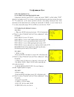
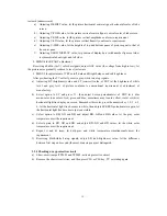
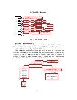
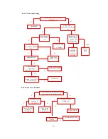
6.2 Existing raster and no picture
Because of the picture video signals and OSD characters display are input to PIN44, PIN15,
PIN16, PIN17 of LA76814(N201), so to observe characters on screen of faulted TV can determine the
approximate area of fault.
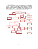
6.3 Existing raster, no picture and sound
Processing according “6.2 Existing raster and no picture” at first, let the picture display normally,
then check sound. About the repair method, see “6.4 Existing raster and picture, no sound”.
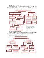
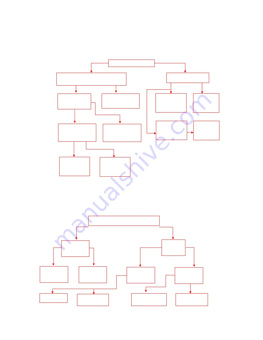
6.4 Existing raster and picture, no sound
N
Y
Y
N
N
Y
Y
N
N
Y
Display OSD characters on screen
When searching automatically channels, check
CVBS waveform existed at N201/PIN(46)
Check 180 V
power supply of
relative plug-in
connector
Check CVBS waveform
existed at N201/PIN44
Check circuit between
PIN(46)~(44) of N201
Check CVBS waveform
at N201/PIN19/PIN20/
PIN21
Check operating status of
TUNER
Check N201
Check CRT board
Check 180 V power supply on
CRT board
Check bus between
N101, N102, N201*
*
•
Whenever open or interconnect on
the bus from CPU to E
2
PROM and
main chip, no picture can occur.
Check FBP waveform
at N201/PIN28
Check external
element connect to
N201/PIN28
Check waveform at two pins of loudspeaker whether
normal
Check waveform
at N304/PIN(3 )
whether normal
Check waveform at
N304/PIN(6)/PIN(8)
whether normal
Check waveform at
N201/PIN1 whether
normal
Check voltage of
volume control at
N304/PIN(5)
Check external
element connected
to N304/PIN(6)/
PIN(8)
Check mute circuit of
CPU/VOL and V108
Check the
loudspeaker and its
connection
Check N304
Check elements between
N201(1)/PIN1 to
N304(3)/PIN
Check SIF circuit at
N201/PIN52/PIN54(2)
/ SIF
Y
N
Y
Y
N
N
Y
Y
N
N
Summary of Contents for 2168
Page 1: ...ATEC PANDA Type 2188 Type 2168 54 cm Color TV Set Service Manual ...
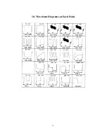
Page 35: ... 34 10 Waveform Diagrams at Each Point ...
Page 38: ... 37 ...
Page 40: ... 39 ...
Page 42: ... 41 ...
Page 44: ... 43 ...
Page 46: ... 45 ...
Page 50: ... 49 ...
Page 52: ... 51 ...
Page 54: ... 53 ...
Page 56: ... 55 ...
Page 60: ......

