background image


  A proper output mode of soun

tched. 

.(Custom, Standard, Music, Movi


EMARK 

d can be selected as per the type of program being wa

e, Speech) 

KEY   

FUNTION 

R

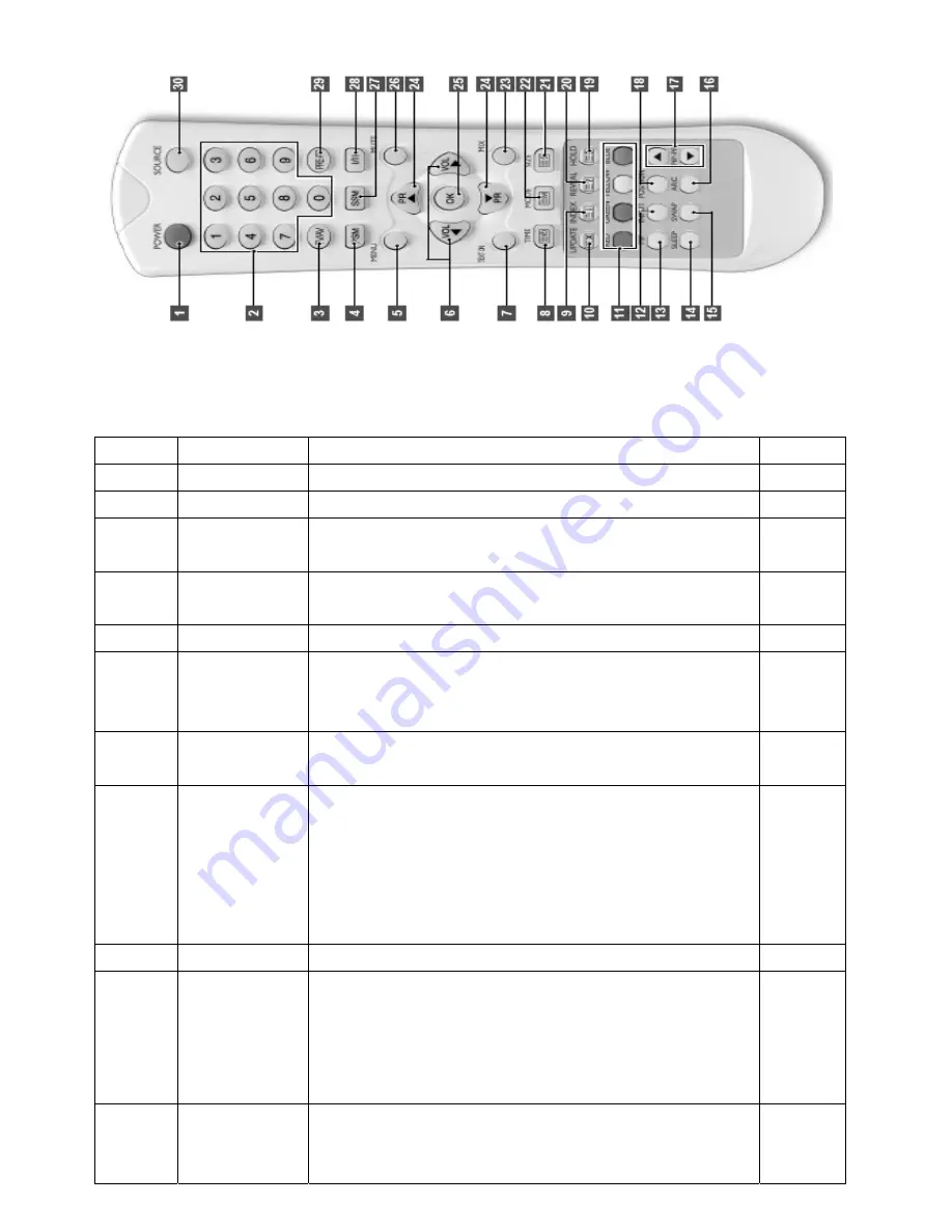
POWER 

Turns the display On or off 


2  NUMBER 


Direct channel select. Direct page selection Teletext display. 

TV/AV   

tton, 


It converts to TV input mode and, if you press and hold the bu
input mode will be switched. 

PSM 

ferred picture setting. (Dynamic, Standard, Game,   

Recalls your pre
Mild, User) 


MENU 


Displays OSD Menu. 

VOL  ◀▶ 

SD 

e sub-menu 


Increases or decreases the volume. Also used to select the O
main menu, to select the OSD main menu, to select th
or to change the values in sub-menus. 

TEXT ON 

 the TV picture, TV mode. 

Changes Teletext mode. Only Teletext mode, text mode 
superimposed on


n. Press the button again to exit the 

TIME 

When viewing a TV program, press this button to display the tim
at the top right corner of the screen. Press the button again to 
remove the display. In Teletext mode press the button to select 
and hold or change a four-digit sub-page number. This is displayed 
along the bottom of the scree
function.   


INDEX 

rrent Page to the INDEX Page. 


Converts from the cu

10 


at the top left corner of the 

ge 

umber. Press this button to view the updated Teletext 

UPDATE 

Displays the TV picture on the screen while waiting for the new
Teletext page. The display will appear 
screen. When the update page is available then display will chan
to the page n
page 


11 

TELETEXT 

REEN key. 

RED: Converts to the Page linked to the RED key. 
GREEN: Converts to the Page linked to the G
YELLOW: Converts to the Page linked to the YELLOW key. 


Summary of Contents for AV32OPD

Page 1: ......

Page 2: ...Specification RGB DVI Spec DTV Mode Spec CHASSIS FUNTION General Spec Engineering Spec 3 Service Mode Adjustment 4 Firmware upgrade 5 Adjustment Standard 6 Remote Controller PAL SECAM 7 Trouble Shooting POWER Trouble SCREEN Trouble SOUND Trouble 8 Block Diagram ...

Page 3: ...hrough the power SMPS when the TV is operating it is dangerous from electric shock to operate the TV with the back cover open Repairing must only be done by a repair technician who has adequate knowledge about the high voltage 5 After completing the service the repair technician must inspect the following electric current leakage to protect the user from electric shock 6 Always check if all the in...

Page 4: ...ere are some semiconductor devices that can be easily damaged by electricity When handling these parts use the static electricity detection device ESD to remove the electrode in the human body Electric current leakage test Cold Check 1 Unplug the AC power and connect the ends of the plug with a wire 2 Turn on the power switch 3 Connect one end of the insulation tester on one of the leads and conne...

Page 5: ...ad wire 4 For this chassis use the cold chassis or insulation transformer for the safety When repairing the power part always use the insulation transformer 5 When operating the TV do not connect or remove the wire 6 Marked parts are important parts to maintain the safety of the part Therefore when exchanging the part always use the designated part S 2 Product Specification Scope This specificatio...

Page 6: ...gnal Text TTX 256 page Power Consumption 160 Watts Power Save Mode Less than 5 Watts Speaker 10 Watts 2 Plug Play DDC 1 2 B Screen Control 16 Colour On Screen Display Menu Bit Map Remote Controller Yes Net 20 1Kg Weight Gross 24 6Kg Others Dimension 932 W 238 D 567 H cm Speaker stand include RGB DVI Mode Spec Resolution H Frequency KHz V Frequency Hz Pixel Frequency MHz Comment 640 350 31 469 70 0...

Page 7: ...768 47 700 60 0 80 136 DTV Mode Spec Resolution H Frequency KHz V Frequency Hz Pixel Frequency MHz Comment 720 480 15 735 59 94 13 500 SDTV DVD 480i 720 576 15 735 50 0 13 595 SDTV DVD 576i 720 480 31 469 59 94 25 175 SDTV 480p 720 576 31 250 50 0 26 566 SDTV 576p 1280 720 44 964 59 94 74 176 HDTV 720p 1280 720 37 500 50 0 60 466 HDTV 720p 1920 1080 33 750 60 0 74 25 HDTV 1080i 1920 1080 28 125 50...

Page 8: ...NT ROL REMOTE Infrared Rays NEC Format Dynamic Standard Mild Game User PSM User Brightness Contrast Color Sharpness CSM CSM Brightness Contrast CSM Normal Warm User PICTURE User Red Green Blue Effect Flat Music Movie Speech User User Bass Treble Surround On Off Normal Spatial AVL On Off AUDIO Balance L 10 0 R 10 PIP POP Source Swap PIP size PIP position PIP POP P BP On Off ON PBP Source Swap Langu...

Page 9: ...12Wrms olume Max POWER 12Wrm V Response Frequency KHz10 100Hz 10 T H D 10 Input 0 7Vrms 4 AMP S N 40dB Type External 5 Speaker Impedance 8Ω System CAM PAL SE Tuning er System Frequency Synthesiz 1 VHF Low 46 25 127 25 Hz M High 133 25 361 25 MHz 2 UHF Channel Hz 367 25 863 25 M System PAL SECAM Tuning esizer System Frequency Synth Channel 1 AIR 55 25 801 25 MHz 2 CATV 6 TV System 5 73 25 799 2 MHz...

Page 10: ...t CONT Do not change the value which is currently set VCTI T CB SA Do not change the value which is currently set CR SAT Do not change the value which is currently set TINT Do not change the value which is currently set R GAIN Do not change the value which is currently set G GAIN Do not change the value which is currently set SCART RGB GAIN B Do not change the value which is currently set 6C R Do ...

Page 11: ...t PANEL Do not change the value which is currently set TUNER Do not change the value which is currently set PIN ON Do not change the value which is currently set OPTION CART s currently set S Do not change the value which i RESET Used to reset to factory default EDID HDCP ON OFF Used to transfer EDID HDCP data NO YES ISP ON OFF Used to update the program NO YES 4 2 Move to Factory Menu using Servi...

Page 12: ...DrvDev Dev_v020201_XP_2000 exe indows2000 Operating System 5 E file CONTENT Write Flash here are two files in DRIVER folder port95nt exe Execute po _v020201_XP_2000 exe Execute setup_LptDrv When you are using W dit the ISP VCT ISP BAT echo echo echo echo REM vctidown wf mst bin vctidown wf s2 SrcCode BinHex VCB4430_1 bin ...

Page 13: ...s bat must be identical In addition the firmware to be updated must be located in the folder of SrcCode BinHex Execute ISP VCT ISP BAT _1 bin 6 wing is shown own If ISP Fail is shown or the follo VctF2Ver txt Boot loader Version 16h RDVER TXT Boot loader Version 03h Then edit ISP VCT VctF2Ver txt Change to 03h If the following is shown RDVER TXT Boot loader Version 03h When the value of 03h is dif...

Page 14: ...e Extended Display Identification Data DDC Display Data Channel download 2 AD9883A Set Adjustment When download is complete success will be shown on the screen ope is standard is applicable to all the models of LCD TV with VCB4430 Chassis main board pecification Since this chassis is non chargeable with insulated power insulated type transformer is not required How n order to protect the adjustmen...

Page 15: ... 1 The information is exchanged without user s command to PC or monitor since they are specified in VESA In other words the function is made for Plug and Play which reconfigures user s environment to be used in no time while automatically communicating with monitor 2 EDID DATA for DVI of VCB4430 EDID table 3 EDID DATA for RGV of VCB4430 EDID table ...

Page 16: ...le of generating 720P Vertical 100 Color Bar Patt Figure 1 Adjustment Pattern 720P Vertical Color Bar 3 Adjustment Method Input 100 Vertical Color Bar Pattern TVBAR_100 in 720P Mode which may be supported for Component input and then select Component1 or Component2 for input and STANDARD for image Wait for more than a second after receiving signal and press S SELECT on adjustment R C Service remot...

Page 17: ...y Teletext mode text mode superimposed on 8 e n Press the button again to exit the TIME When viewing a TV program press this button to display the tim at the top right corner of the screen Press the button again to remove the display In Teletext mode press the button to select and hold or change a four digit sub page number This is displayed along the bottom of the scree function 9 INDEX rrent Pag...

Page 18: ...hanged 20 REVEAL Shows letters that are hidden not displayed 21 SIZE even though they are included in the currently displayed Page Selects letters that are hidden not displayed 22 MODE Toggles between list mode and current Text mode FLOF TOP or normal 23 MIX The teletext pages and the TV picture are displayed simultaneously on both sides of the screen 24 PR TELETEXT PREVIOUS NEX T PAGE Press PR to...

Page 19: ...ndby Voltage Check Chassis VCB4430 Connector J701 PIN 1 5V check Replace CHASSIS VCB3000 Check Power ref Voltage Check Power CN401 in 1 2 Check Chassis VCB3000 U706 LT1117 Check Standby Voltage Pass Fail Fail Fail Fail Pass The Power of SUB POWER master SW BOARD is OK Replace SUB POWER BOARD Fail Pass Replace Power Board Pass Press POWER ON S W ...

Page 20: ...tandby Voltage Check Chassis VCB4430 Connector J701 PIN 1 Check Power ref Voltage Check Power CN401 Check Standby Voltage Check Chassis VCB4430 U706 LT1117 PIN 2 3 3V check Fail Fail Replace Power Board Fail Pass CHASSIS VCB4430 The Power of SUB POWER BOARD is OK Replace SUB POWER BOARD Fail Pass Pass Pass Fail ...

Page 21: ...R J701 PIN 1 5V PIN 5 INV ON PIN 9 10 12V are OK POWER BOARD REF CN401 PIN 1 5V PIN 5 INV ON PIN 9 10 12V are OK Replace Power Board After Allowing AC Power Press Sub Power Button and Then Press Power of Remote or OSD Button Is There an Image Fail Replace CHASSIS VCB4430 Pass Pass Pass Pass Fail Fail Replace Power Board ...

Page 22: ...CB4430 BOARD Check Output of Speaker Check if there is output signal of PIN 1 in VCB4430 board J41 J42 Fail Pass Pass Check Power of Sound supply Check U502 PIN 33 12V in VCB4430 BOARD Check 12V of L701 Inductor POWER BOARD REF CN401 PIN 1 5V PIN 5 INV ON PIN 9 10 12V are OK Fail Check CHASSIS VBC3002 BOARD Fail Check CHASSIS VBC3002 BOARD Fail Pass Pass Pass ...

Page 23: ...8 Block Diagarm ...

Page 24: ...9 Circuit Diagram ...

Page 25: ... Main board ...

Page 26: ......

Page 27: ......

Page 28: ......

Page 29: ......

Page 30: ......

Page 31: ......

Page 32: ... POWER BOARD SMPS ...

Page 33: ... HO 2 0mm STRAIGHT 2 J41 J42 7 WAFER SMW200 3 3P YEON HO 2 0mm STRAIGHT 2 J912 J915 8 WAFER SMW200 4 4P YEON HO 2 0mm STRAIGHT 1 J909 9 WAFER SMW200 5 5P YEON HO 2 0mm STRAIGHT 1 J45 10 WAFER SMW200 10 10P YEON HO 2 0mm STRAIGHT 1 J33 11 TUNER TECH2949PG40B PAL SAMSUNG 1 U639 12 SAW FILTER EPCOS X6966M M100 IF filter for digital cable TV PAL 용 1 U603 13 AXIAL INDUCTOR AL04TB 122K 1 2mH 44MA 5 0MM ...

Page 34: ...5 C156 C157 C158 C159 C160 C161 C163 C164 C165 C167 C168 C169 C175 C177 C178 C179 C209 C301 C302 C303 C304 C305 C306 C307 C308 C309 C310 C311 C312 C314 C318 C319 C320 C321 C324 C325 C326 C329 C330 C334 C335 C336 C337 C338 C340 C341 C342 C343 C344 C346 C364 C413 C521 C522 C523 C525 C528 C705 C706 C710 C711 C713 C715 C718 C720 C721 C722 C728 C730 C739 C775 C776 C777 C778 C779 C781 C782 C783 C784 C78...

Page 35: ... J 1608 D R TP 2 R536 R603 31 CHIP RESISTOR 6 8K 1 10W J 1608 D R TP 3 R336 R337 R338 32 CHIP RESISTOR 5 1K 1 10W J 1608 D R TP 2 R549 R550 R103 R114 R115 R116 R117 R171 R218 R243 R244 R245 33 CHIP RESISTOR 4 7K 1 10W J 1608 D R TP 19 R301 R302 R470 R472 R772 R936 R951 R982 R983 34 CHIP RESISTOR 3 3K 1 10W J 1608 D R TP 3 R532 R929 R974 35 CHIP RESISTOR 2 2K 1 10W J 1608 D R TP 1 R277 36 CHIP RESI...

Page 36: ...L510 L709 52 CHIP BEAD HH 1M2012 121 CERATEC 2012MM R TP 12 L713 L714 53 IC INTERGRAL REGULATOR 1 0A 1 8V IL 1117 18 2 U704 U705 54 IC INTERGRAL REGULATOR 1 0A 2 5V IL 1117 25 2 U713 U714 55 IC INTERGRAL REGULATOR 1 0A 3 3V IL 1117 33 3 U706 U715 U716 56 IC INTERGRAL REGULATOR 1 0A 5 0V IL 1117 50 1 U95 57 TRANSISTOR A1504 SOT23 2 Q905 Q906 Q101 Q102 Q203 Q204 Q209 Q210 Q212 Q213 Q501 Q502 58 TRAN...

Page 37: ...52 SOP 16P 1 U307 80 DIODE UDZ S 33B TP ROHM K SOD323 2 ZD707 ZD708 ZD506 ZD507 ZD508 ZD509 ZD510 ZD902 ZD903 ZD904 ZD905 ZD90 7 ZD908 ZD909 ZD910 ZD911 ZD912 ZD913 ZD914 ZD915 ZD916 ZD91 7 ZD918 ZD919 ZD920 ZD921 ZD922 ZD923 ZD924 ZD925 ZD926 ZD92 7 ZD928 ZD929 ZD930 ZD931 ZD932 ZD933 ZD934 ZD935 ZD936 ZD93 7 ZD938 ZD939 ZD940 ZD941 ZD942 ZD943 ZD944 ZD945 ZD946 ZD94 7 81 DIODE ZENER UDZ S 5 6B T...

Page 38: ... Power Board SMPS ...

Page 39: ......

Page 40: ......

Page 41: ...11 Assembly Diagram ...

Page 42: ......

Reviews: