background image


17 

56 

01 0275 07 

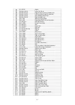
Engine 

57 

86R 03 000-CE 

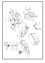
Lathe Unit Group 

58 

86R 03 001-CE 

Right Connection Group Of Lathe Unit 

59 

86R 03 002-CE 

Left Connection Group Of Lathe Unit 

60 

86R 03 003-CE 

Sport Skidding Metal Sheet 

61 

86R 03 004-CE 

Sport Handling Axle 

62 

84 03 005 

Bearing Stopping Plate 

63 

84 03 006 

Supporting Plate For Arm Connection 

64 

01 0073 025 

Imbus Bolt Screw   

65 

84 03 007D 

Fixing Screw Group 

66 

01 0064 025 

Bolt 

67 

01 0315 005 

Swivel Arm 

68 

01 0139 017 

Segment 

69 

01 0053 06203-FAG 

Bearing 

70 

01 0315 004 

Wheel 

71 

84 03 007A 

Body Group 

72 

84 03 007B 

Sport Turning Plate 

73 

84 03 007C 

Slider Locking Plate 

74 

84 03 007E 

Square Nut 

75 

01 0074 070 

Imbus Bolt Screw   

76 

01 0074 035 

Imbus Bolt Screw   

77 

01 0050 01 

Fixed Sport 

78 

01 0047 02 

Tool Bit ( Lathe Cutter ) 

79 

01 0083 90 

Bolt 

80 

15 37 001 

Grooving Holder Connecting Equipment 

81 

01 0114 05 

Lathe Unit To Stop Switchcrank 

82 

86R 05 000-CE 

Hydraulic Unıt Group


83 

01 0159 27 

Power Unit 

84 

01 0014 176 

Record Body 

85 

01 0131 1-4 

Copper Flake 1/4 

86 

01 0014 79 

Record Thimple 

87 

01 0014 23C 

Pipe Squeezing Nut 

88 

01 0131 3-8 

Copper Flake 

89 

01 0014 20 

Record Body 

90 

84 07 001 

Hydraulic Unıt Connection Sheet Metal 

91 

01 0112 06 

Washer 

92 

01 0061 020 

Bolt 

93 

01 0117 006 

Fiber Nut 

94 

01 0112 08 

Washer 

95 

01 0115 008 

Nut 

96 

15 30 001 

Valve Lever Shaft 

97 

01 0014 21 

Record 

98 

01 0157 01 

Hydraulic Valve 

99 

86R 05 001-CE 

Pressure Pipe 

100 

86R 05 002-CE 

Discharge Pipe 

101 

01 0016 1800 

Hydraulic Hoses 

102 

86R 04 000-CE 

Cabin Group


103 

86R 04 001-CE 

Cabin Right Body Group 

104 

86R 04 002-CE 

Cabin Left Body Group 

105 

84 05 003 

Cabin Top Body Group 

106 

86R 04 003-CE 

Cabin Inner Cover Plate 

107 

86R 04 004-CE 

Cabin External Cover Plate 

108 

01 0039 121 

Top Cover. 

109 

01 0030 49 

İgnition 

110 

01 0030 73 

İgnition 

111 

01 0030 20 

Hydraulic Unit Start-Stop Switch 

112 

01 0030 95 

Button 

113 

01 0030 97 

Button 

Summary of Contents for KONIG NEWLINE Series

Page 1: ...INSTRUCTIONS BOOKLET Rim Press Lathe KÖNİG NEWLİNE English ...

Page 2: ...2 ...

Page 3: ... If the Material and production fault is found the damaged parts will be replaced with new one Warranty covers all parts of the machine during the warranty ATTENTION you have to put thermic switch which is suitable to motor ampere on your electric wiring to make Electric motor under warranty otherwise in case of any defect the Electric Motor will not be under warranty Do Make Maintanence of the ma...

Page 4: ...onserve this booklet carefully for further consultation THIS MACHINE Is a rim pres to repair defective rims The machine has been designed to operate within the limits described in this booklet and in accordance with the manifacturers instructions The machine must be used only for the functions for which it was expressly designed Any other use is considered wrong and therefore unacceptable The mani...

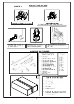
Page 5: ...rovided accessories When the machine arrives check that it has not been damaged during transport and that all the accessories are present 7 Rim to center washer 1 54 2 56 5 3 57 4 58 5 59 5 6 60 1 7 63 3 8 64 9 65 10 66 6 11 72 12 72 5 CLAUSE 3 1 12 pcs connetıng flanches for different sizes of rims 2 1 pcs gauge 3 5 pcs allen head wrenches 4 1 pcs angular supports 1 pcs sguare supports small 1 pc...

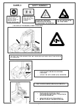
Page 6: ...E If the operator hears unusual noises or vibrations or something that may be dangerous he must immediately press the emergency button and switch off the main switch and check the section Malfuctions causes and possible remedies in the instructions manual If the problem is still call the service Wear protection glasses and gloves during the operation Stand straigth during operation Work in an insu...

Page 7: ...T PINS ARE MOUNTED AND CHECK THAT THE PISTON IS IN THE CANAL TIGHT THE FIXING HANDLE DURING LATHE OPERATION DO NOT USE JETS OF WATER STEAM HIGH PRESSURE WASH UNITS SOLVENTS NEAR THE RIM REPAIR MACHINE UNPLUG OR SWITCH OFF THE MAIN SWITCH BEFORE YOU START CLEANING THE MACHINE PLEASE READ THE İNSTRUCTİONS MANUAL CAREFULLY BEFORE START USİNG THE MACHİNE DON T USE YOUR MACHINE WITHOUT GLASSES AND GLOV...

Page 8: ...and its connections 4 Switch on the mains 5 Replace the fuse The pressure of the hydraulic unit is not enough 1 The rotation of the hydraulic engine is reverse 2 There is leak of oil in the connections 3 There is lack of oil in the hydraulic engine 1 Reverse the two wires in the connection plug 2 Check the couplings change them if necessary 3 Put some oil till the level to the hyraulic engine CLAU...

Page 9: ...te Connect the cable to a plug that conforms with European norms or to the norms of the country in which the machine used The plug must have an earth terminal Check that the earth connection is effective The machine must be connected to the mains through a multipole isolating switch which conforms with European norms and with contact openings of at least 3 mm Check that the multipole connector on ...

Page 10: ...ecting flansh for the rim 3 Tight the connecting flansh and fasten to the suitable canals on the flansh ANALYSING THE DEFECTIVE AREA 1 Rotate the flansh 2 Locate the defective area by using gauge and sign it 3 Tıght The Nuts To Start The Repaırıng Procedure 4 Choose a suitable support and repair it by using the pres RIM REPAIRING POSITIONS CLAUSE 10 ...

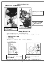
Page 11: ... 3 Your personel safety If the rim is too defected first mend it with the lever and then repair it with the pres LATHE OPERATION TIGHT THE FIXING HANDLE DURING LATHE OPERATION UNTIGHT THE NUTS DURING LATHE OPERATION Lathe operation this procedure is for cleaning the burrs and the overplus parts of the welding operation If the defect is from inner to the outer side of the rim If the defect is on th...

Page 12: ... having unplugged it from the mains TECHNICAL ASSISTANCE AND SPARE THE MACHINE IS GURANTEED 1 YEARS FOR ANY MACHINE MAFUNCTIONS CONSULT THE SECTION MALFUCTIONS CAUSES AND POSSIBLE REMEDIES ANY OTHER MALFUNCTIONS MUST BE CHECKED BY PROFESSIONALLY QUALIFIED PERSONNEL IN ALL CASES CONTACT THE ASSISTANCE SERVICE OF HATCO FOR PROMPT ASSISTANCE IT IS IMPORTANT AT THE TIME OF THE CALL TO SPECIFY THE MACH...

Page 13: ...13 MP MP MP 5 V U W V U 9 8 7 6 4 W 3 2 1 SWITCH ELECTRICAL PLAN CLAUSE 13 ...

Page 14: ...14 DEMONTAGE PLAN CLAUSE 13 01 0275 07 ...

Page 15: ...15 ...

Page 16: ... 25 23 12 001 Main Shaft 26 15 10 001 Occurente Ring Back Cover 27 23 13 001 Bearing Fixing Nut 28 23 14 001 Reduction Connection Flange 29 15 08 001 Rim Connect Flash 30 26 10 00 Centering Washers 31 15 15 000 Piston Pendent 32 01 0024 020 3 O Ring 33 15 14 004 Nut 34 01 0021 35 46 3 10 Wipper 35 01 0024 060 3 O Ring 36 01 0024 035 3 O Ring 37 01 0022 060 044 Compact Set 38 15 14 003 Hydraulic Cy...

Page 17: ...pment 81 01 0114 05 Lathe Unit To Stop Switchcrank 82 86R 05 000 CE Hydraulic Unıt Group 83 01 0159 27 Power Unit 84 01 0014 176 Record Body 85 01 0131 1 4 Copper Flake 1 4 86 01 0014 79 Record Thimple 87 01 0014 23C Pipe Squeezing Nut 88 01 0131 3 8 Copper Flake 89 01 0014 20 Record Body 90 84 07 001 Hydraulic Unıt Connection Sheet Metal 91 01 0112 06 Washer 92 01 0061 020 Bolt 93 01 0117 006 Fib...

Page 18: ...1 380 50 Portable Support 123 01 0112 12 Washer 124 01 0064 070 Bolt 125 01 0117 012 Fiber Nut 126 15 13 001 Hydraulic Cylinder Supports Pin Set 127 14S 04 001 Down Support 128 84 01 005 Electrical Panel Group 129 84 01 005A Connection Plate 130 01 0202 03 Transformer 131 01 0196 27 Contactor 132 01 0028 42 Cable Canal 133 01 0028 64 Klemenes Rail 134 01 0028 42 K Cable Canal Cover 135 01 0028 26 ...

Reviews: