Chapter 1. Introduction
11
PE5108B / PE5108G / PE5208B / PE5208G / PE7108B /
PE7108G / PE7208B / PE7208G Readout Section
No.
Item
Description
1
Circuit Breaker
Pushbutton
As a safety measure, if there is an overcurrent situation regarding the
device’s power, the circuit breakers will trip. Press the button to
recover normal operation.
2
Power Sockets
8 x IEC320 C13 or 7 x IEC320 C13 + 1 x C19
Note:
Holes for ATEN Lok-U-Plug cable holders are located around
the sockets. See
, page 19, for further
information.
3
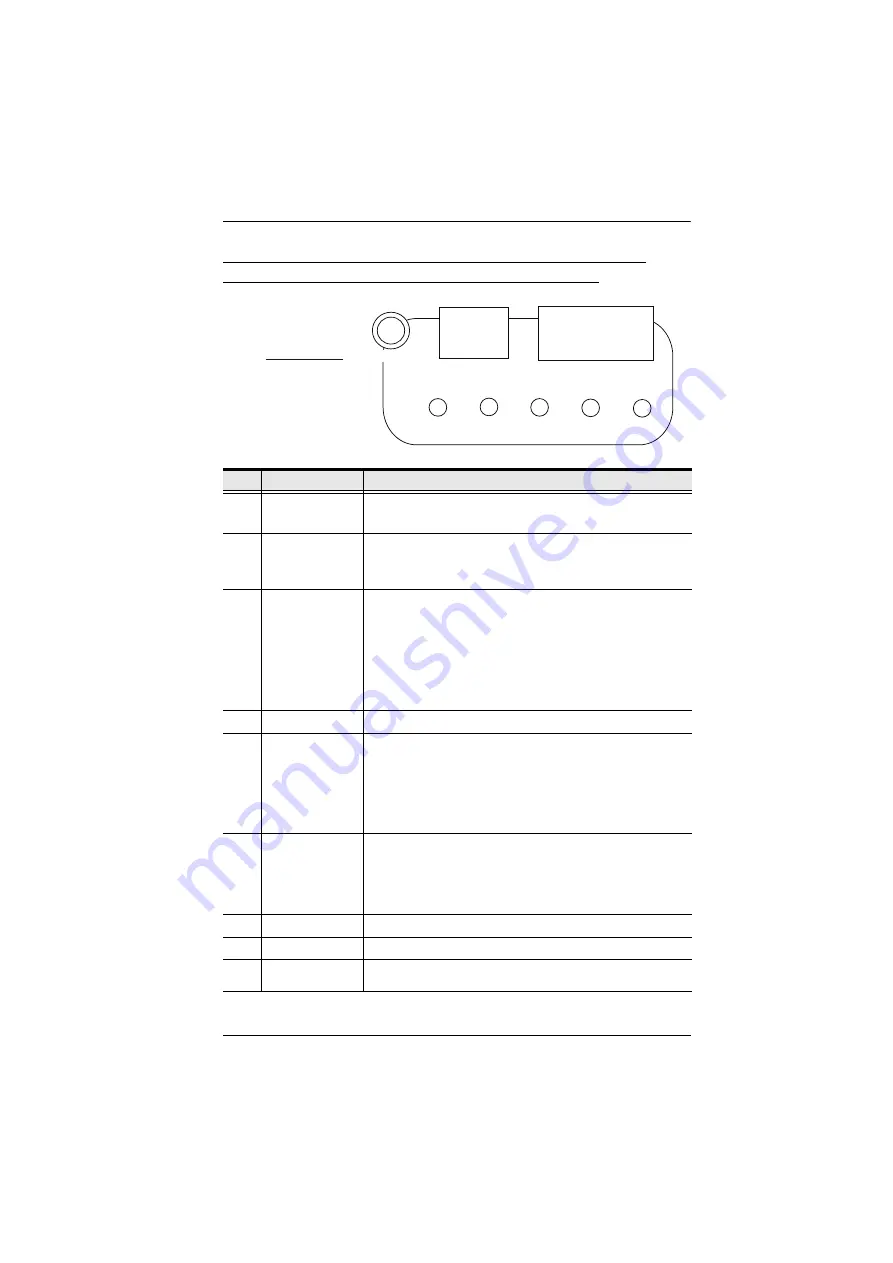
Readout Section
The selection (PDU Current / Outlet Current / IP Address) appears
in the first (1-digit) display window.
PDU Current / Outlet Current / IP Address appear in the second
(3-digit) display window
The LEDs above the items indicate which one the readout relates
to.
Press the button next to the first display window to cycle the
selection among the items.
4
Power LED
The LED lights when the eco PDU is ready to operate.
5
LAN Port and
LEDs
The cable that connects the eco PDU to the LAN plugs in here. The
Link and LAN LEDs are built into the LAN port:
Link
: Lights GREEN to indicate that a connection via the eco PDU's
RJ-45 Ethernet port has been established. Flashes to indicate data is
being transmitted.
LAN
: Lights ORANGE to indicate 10 Mbps data transmission speed.
The LED lights GREEN to indicate 100 Mbps data transmission
speed.
6
Reset Switch
This switch is recessed and must be pushed with a thin object, such
as the end of a paper clip.
Press and release to reboot the device.
Press and hold for more that three seconds to reset the eco
PDU to its factory default settings
7
Grounding Terminal The wire used to ground the unit connects here.
8
Sensor Ports
External sensors plug into these two RJ-11 ports.
9
Power Socket
The power cord that connects the unit to an AC power source plugs
in here.
3
S E L E C T
PDU
CURRENT
OUTLET
CURRENT
IP
ADDRESS
SENSOR
1
SENSOR
2


