KL1108V / KL1116V User Manual
19
Single Stage Installation
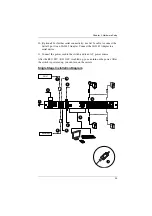
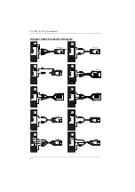
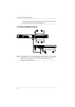
In a Single Stage installation, there are no additional switches cascaded down
from the first unit. To set up a single stage installation, refer to the installation
diagrams beginning on the following page (the numbers in the diagram
correspond to the numbers of the installation steps), and do the following:
1. Ground the KL1108V / KL1116V by connecting one end of a grounding
wire to the grounding terminal, and the other end of the wire to a suitable
grounded object.
Note:
Do not omit this step. Proper grounding helps to prevent damage to
the unit from surges or static electricity.
2. (Optional) If you choose to install an external console, plug your
keyboard, monitor, and mouse into the
Console Ports
located on the
switch’s rear panel. The ports are color coded and marked with an icon to
identify themselves.
3. For each of the computers you are installing, use Cat 5e cable to connect
any available KVM port to a KVM adapter cable that is appropriate for the
computer you are installing. (See
adapter cable details.)
Note:
The maximum supported distance to the adapter cable is 50 m.
4. Connect the KVM Adapter cable to the computer. Refer to the
, page 21, to plug the adapter cable connectors
into their respective ports on the computers you are installing.
5. Plug the LAN cable into the KL1108V / KL1116V’s LAN 1 port.
6. (Optional) Plug another cable from the LAN into the KL1108V /
KL1116V’s LAN 2 port.
7. (Optional) Use Cat 5e cable to connect the PON port to an SA0142
Adapter. Connect the SA0142 Adapter to the PON IN port of a Power
Over the NET™ unit.
8. (Optional) Use Cat 5e cable to connect the Modem port to an SA0142
Adapter. Connect the SA0142 Adapter to a modem’s DB-9 port.
9. (Optional) For serial connectivity, use Cat 5e cable to connect the Serial 1
port to an SA0142 Adapter. Connect the SA0142 Adapter to a serial
device.


