background image

Sheet # 692/1u – 

Electric connectors (F610)


Version 1.04a 

User guide 

ATEQ 6th series

 Page 2/7 

3. ELECTRIC CONNECTORS 

3.1. S

UPPLY THE DEVICE WITH 

24


V


DC 

Two means are available to supply the device following its configuration.  

3.1.1.  Supply the device with 24 V DC - 2A on the M12 connector 


Plus the fitted power supply to the dedicated M12 Connector. 

¾

  Pin 2 : + 24 V DC.  

¾

  Pin 4 : ground 0 V. 

3.1.2.  Supply the device with 24 V DC - 2A on the relay board 


Connect by using the following mean: 

¾

  24 V DC on the pins 2 or 4. 

¾

  0 V on the pin 16. 

See the paragraph 4.2. "

Connector I/O all or nothing

". 

3.2. RS232


C

ONNECTOR PRINTER 

/


M

ODBUS OR 

P

ROFIBUS


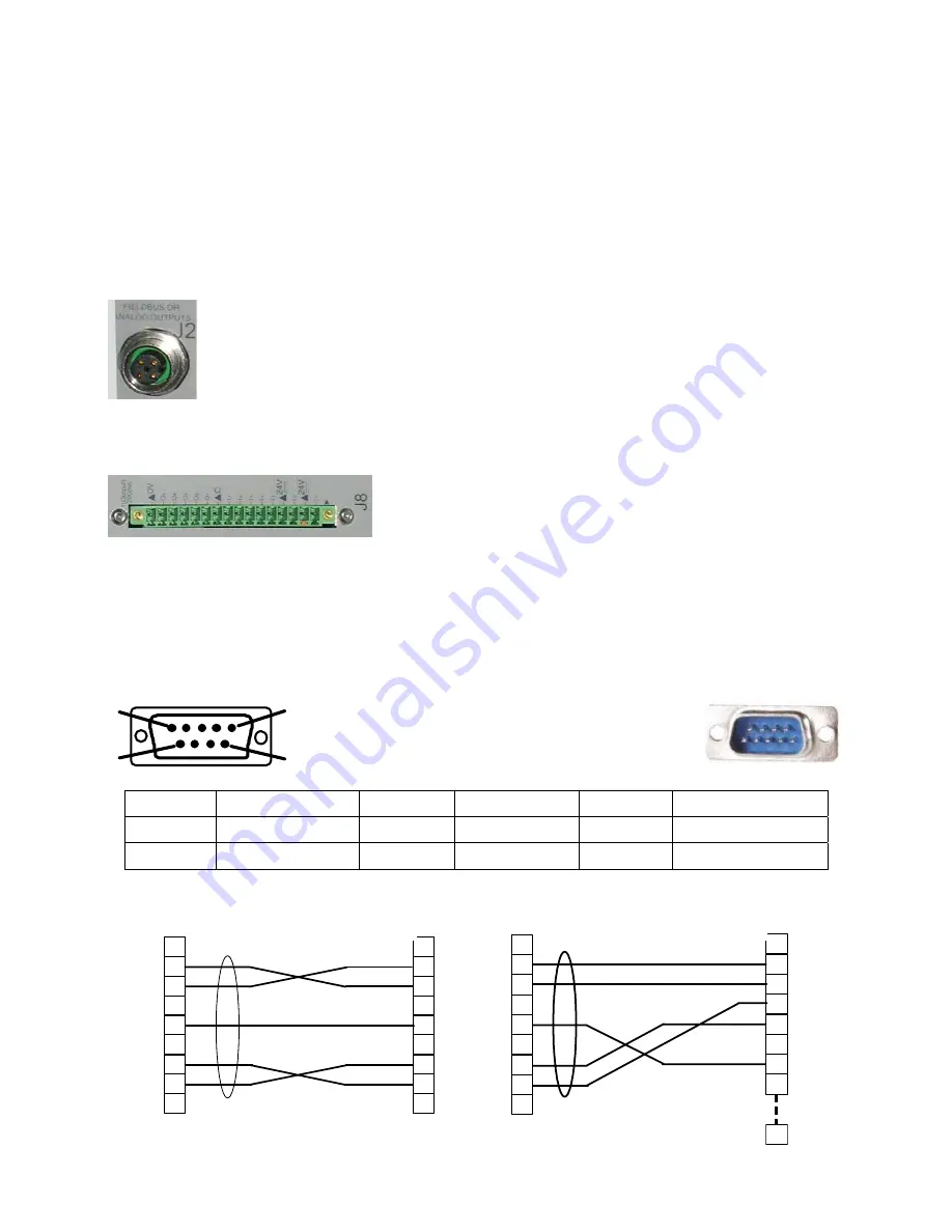
3.2.1.  Connector in RS232 mode 

1

5

9

6

RS232

: SubD 9 points male connector. To plug 

a printer, a bar code reader, a PC, a save 
module. 


Pin 1 

Not used 

Pin 4 

Not used 

Pin 7 

RTS request to send 

Pin 2 

RXD data input 

Pin 5 

Earth/Ground 

Pin 8 

CTS clear to send 

Pin 3 

TXD data output 

Pin 6 

Not used 

Pin 9 

Not used 

3.2.1. 1)  Examples of RS232 cables 


1
2
3
4
5
6
7
8
9

ATEQ 

User

9 pin SubD 

connector 

9 pin SubD

connector

RX 

TX 

GND 

RTS 

CTS 

RX
TX

GND

RTS

CTS


1
2
3
4
5
6
7
8
9

1
2
3
4
5
6
7
8

ATEQ

User

25

9 pin SubD

connector 

25 pin SubD

connector 

RX 

TX 

GND

RTS

CTS

RX 

TX

GND

RTS
CTS


Summary of Contents for 6th series

Page 1: ...s are located under the rubber cover USB connector to plug a PC USB connector to plug an UBS memory key or a remote control The USB connector rubber cover can be slightly deviated to the front for easy access to connectors Do not plug two USB components together 2 LOWER SIDE CONNECTORS Example of lower side face Note following the versions and the purchase options the customer device may be differ...

Page 2: ...V on the pin 16 See the paragraph 4 2 Connector I O all or nothing 3 2 RS232 CONNECTOR PRINTER MODBUS OR PROFIBUS 3 2 1 Connector in RS232 mode 1 5 9 6 RS232 SubD 9 points male connector To plug a printer a bar code reader a PC a save module Pin 1 Not used Pin 4 Not used Pin 7 RTS request to send Pin 2 RXD data input Pin 5 Earth Ground Pin 8 CTS clear to send Pin 3 TXD data output Pin 6 Not used P...

Page 3: ...3 DEVICENET PROFINET OR ETHERNET CONNECTORS OPTION 3 3 1 Devicenet Input option 2 1 4 3 5 To connect to others ATEQ devices M12 male connector 3 3 2 J2 Devicenet output option 2 1 4 3 5 To connect to others ATEQ devices M12 female connector 3 3 3 Wiring Devicenet Pin 1 Drain Pin 3 V Pin 5 CAN_L Pin 2 V Pin 4 CAN_H 3 3 4 Input and output Profinet 4 3 1 2 5 Ethernet M12 pin assignement M12 female D ...

Page 4: ...OPTION 1 2 3 4 5 6 7 8 9 10 11 12 1314 15 16 Output inputs codes Pin 1 COMMUN Outputs 1 2 3 24 V DC Pin 2 Output n 1 open collector Pin 3 Output n 2 open collector Pin 4 Output n 3 open collector Pin 5 COMMON Outputs 4 5 6 24 V DC Pin 6 Output n 4 open collector Pin 7 Output n 5 open collector Pin 8 Output n 6 open collector Output codes 24V DC 100mA Max Pin 9 Input 0 NPN or PNP Pin 10 Input 1 NPN...

Page 5: ...eference part Output 3 Pass part cycle 2 14 Output 4 Alarm Output 4 Fail part cycle 2 Alarm 15 Output 5 End of cycle Output 5 End of cycle 16 0 V 0 V Outputs dry contacts 60V AC DC Max 200mA Max The compact mode is a software function which is activated in the CONFIGURATION AUTOMATISM CHANGE I O OUTPUT menu 4 2 1 Connector I O Inputs Outputs graphical representation 4 2 1 1 PLC in NPN mode connect...

Page 6: ...er supply provided by the customer In the case of customer external supply the ATEQ instrument can be supply by the 2 and 4 pins on the J3 connector too 4 2 1 3 Lights connection I1 Reset Customer Inputs board 16 32 programs I2 Start I3 Pr 1 1 I4 Pr 2 1 Good part Common Test fail part Reference fail part Alarm End of cycle 24 V DC I6 Pr 8 1 I5 Pr 4 1 I7 Programmable input 16 15 14 13 12 11 10 9 8 ...

Page 7: ...V 0 3 A maximum Combinations of pins to activate to select programs Program number I Oconn Pin 5 input 3 I O Conn Pin 6 input 4 I O Conn Pin 7 input 5 I O Conn Pin 8 input 6 I O Conn Pin 9 input 7 Extens Pin 1 input 8 Extens Pin 2 input 9 1 0 0 0 0 0 0 0 2 1 0 0 0 0 0 0 3 0 1 0 0 0 0 0 4 1 1 0 0 0 0 0 5 0 0 1 0 0 0 0 6 1 0 1 0 0 0 0 7 0 1 1 0 0 0 0 8 1 1 1 0 0 0 0 9 0 0 0 1 0 0 0 10 1 0 0 1 0 0 0 ...

Reviews: