QSG_F6CLASS.376.00_EN_01 / 2019-03-25
12 / 32
DIGITAL LINKS
PC USB connectors (on front face)
USB connectors can be used for connecting miscellaneous compatible USB devices.
The USB connectors are located under the rubber cover 1
(see figure).
1
Rubber cover
2
USB connector to PC
3
USB connector to USB key
Do not connect two USB devices at the same time.
Do not use a cable longer than 2 m.
Push the rubber cover
1
slightly forward for an easy access to USB connectors
2
and
3
.
Only use this connection for temporary communication. Connection to a PC cannot be used
permanently because the communication can be disconnected by the PC.
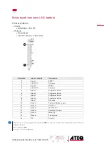
Printer RS232 connector / Modbus (option)
RS232 - SubD 9 pins male connector (printer) (J12)
RS232 for printer, barcode reader, PC connection.
Pin number
Signal
1
Not used
2
RXD data input
3
TXD data input
4
Not used
5
Ground
6
Not used
7
RTS request to send
8
CTS clear to send
9
Not used
DIGITAL INPUTS/OUTPUTS
The 24V DC power supply for the digital inputs can be provided by 2 means:
— The internal power supply of the device (0.3A max)
— An external power supply provided by the customer.
Inputs default mode is PNP. NPN mode is available on request.

