background image

2

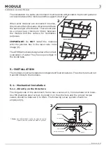
3.-

4.-POSITIONING AND INCLINATION

x

x
x
x
x
x
x
x
x
x
x
x

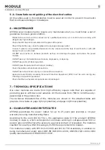
NO debe intentar reparase ni emplearse ningún modulo roto, ya que el contacto con alguna parte de
este puede provocar en una electrocución.

NO exponer directamente la parte trasera a la luz solar.

Work ONLY under dry conditions, with dry modules and Insulated tools.

Do NOT install the module where flammable gases or vapors are present.

Do NOT drill holes in the frame or glass of the module.

Do NOT treat back sheet and front surface of the module with paint and adhesives.

Do NOT artificially concentrate light on the module.

Do NOT wear metallic jewelry while installing or trouble shooting the module.

Do NOTdisassemble, modify or adapt the module or remove any part of the module.

Be sure to completely ground all modules.

Do not touch terminals while module is exposed to light or during installation.

The connectors must be protected from dust, sund, wather,..., If the connectors are to remain
disconnected in the field.

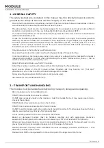
The modules may be installed on plots of land, terraces, roofs and patios. ATERSA
provides a series of accessories for installations on façades, windows, balconies, walls
and cornices.

In order to ensure optimum performance the modules must not be placed in the shadow
of other objects (plants, snow, buildings, construction elements, other modules, etc.),
at least during the main hours of daylight.

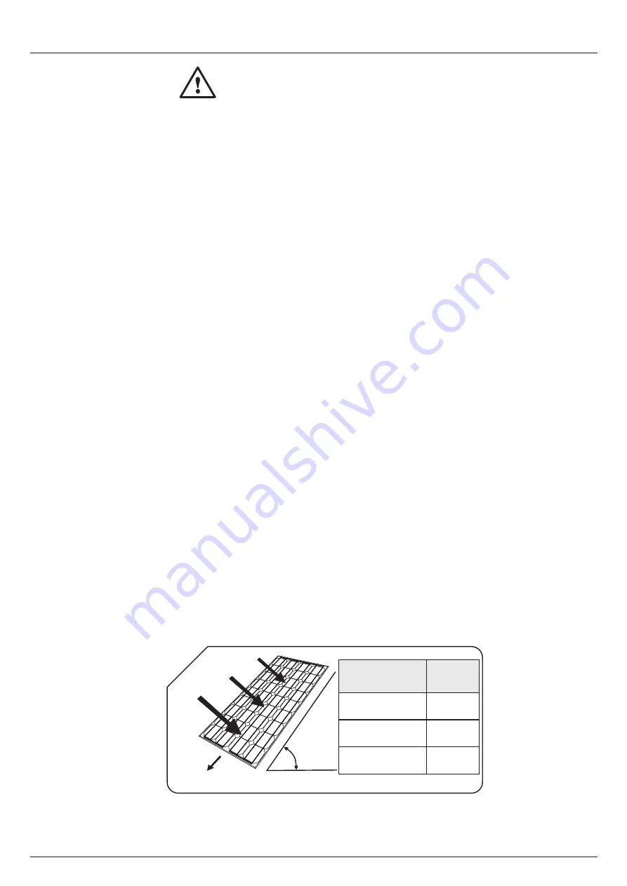
The panels must face south if installed in the northern hemisphere.Guidelines for
achieving maximum annual power output from a fixed installation are provided below. A
design period will be established in order to calculate the size of generator in accordance
with the consumption requirements and radiation. To determine the optimum
inclination we will use the following table (1):

Do not install the solar module in a location where it could be immersed in water or
continually exposed to water, e.g. from a sprinkler.

WARNINGS

Failure to follow these instructions could result in the destruction of the equipment or
personal injury.

HORIZONTAL

INCLINATION

SOLAR LIGHT

SOUTH
(North hemisphere)

INCLINATION

WINTER

DESIGN PERIOD

SUMMER

ANNUAL

La10º

Latitude -20º

Latitude -10º

1

MODULE

Installation and User Manual

EN-MU-41 (4)-E

Summary of Contents for A-150M

Page 1: ...A VALENCIA P Industria Juan Carlos I 46440 Almussafes Valencia Spain Tel 902 545 111 Fax 902 503 355 Avda de la Foia 14 MODULE Installation and User Manual www atersa com Last revision 17 01 2017 Prin...

Page 2: ...ng installation or maintenance 1 GENERAL SAFETY 1 2 TRANSPORT AND HANDLING 1 3 WARNINGS 2 4 POSITIONING AND INCLINATION 2 5 INSTALLATION 3 7 8 6 MAINTENANCE 8 7 TECHNICAL SPECIFICATIONS 8 8 GUARANTEE...

Page 3: ...of module back sheet with sharp objects as scratches may directly affect product safety Do not use the junction box to hold or transport the module Broken or damaged modules must be handled carefully...

Page 4: ...installed on plots of land terraces roofs and patios ATERSA provides a series of accessories for installations on fa ades windows balconies walls and cornices In order to ensure optimum performance t...

Page 5: ...dent fixed structures The structure must not transmit stress to the modules The longest side of the aluminium frame has a series of 6 7mm diameter drill holes Use M6 stainless steel screws to install...

Page 6: ...d on standard structures U type guide rail or guide insertion Fixing on standard structures is carried out using the dead end clamp the M8x20 serrated head Allen screw flat washer and M8 nut View imag...

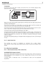
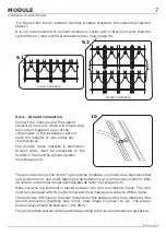
Page 7: ...icable regulations 5 2 Electrical Installation CABLE SECTION Copper section Put the first two fixing sets in place and ensure they are vertically aligned Fully tighten the Allen screw 6 Attach the oth...

Page 8: ...ion to the polarity of the wires Make sure that the cable is inside the clip and is fixed correctly if the cable is not installed correctly the juntion box will be deteriorated electric arc After term...

Page 9: ...e 4mm View image of annex 11 12 The proper torque values should be between 1 5 to 2Nm The photovoltaic system will be earthed according to the local and national regulations 2 It is not recommended to...

Page 10: ...nvolve working with dangerously high voltages Check that dirt has not accumulated on the glass of the panel Should this be the case clean the glass with a sponge and soapy water In case if water is no...

Page 11: ...TYCO IP65 15 2 20 25 A 18A 45V 175 C m A 260P A 265P A 290P A 295P A 300P 300 W 15 42 8 21 A 8 89 A 44 97 V 36 52 V A 305P 305 W 0 5 W 15 67 8 27 A 8 78 A 45 97 V 36 88 V A 310P 310 W 0 5 W 15 93 8 35...

Page 12: ...0 5 W 15 97 8 44 A 8 99 A 37 90 V 30 79 V 0 5 W 15 35 8 24 A 8 79 A 37 62 V 30 35 V 255 W 260 W 250 W A 250M A 255M A 260M 16 27 8 54 A 9 04 A 38 40 V 31 03 V 0 5 W 265 W A 265M A 310M 0 5 W 15 94 45...

Page 13: ...tion and User Manual Printed on recycled paper UNE EN ISO 14001 UNE EN ISO 9001 ER 0979 1997 GA 2009 0396 OHSAS 18001 SST 0134 2012 Dispose of the device at an environmental disposal point when it rea...

Page 14: ...ded for the fixation of the laminate and ensure proper installation Always use fastening systems that do not damage the laminate module A 80 mm 11 mm B 13 mm 9 mm B 10 mm 6 4x9 6 4x9 225 25 0 595 25 0...

Page 15: ...9 mm B 10 mm 6 4x9 6 4x9 General dimensions Monocrystalline modules Module Laminate ANNEX Dimensions in mm The areas marked in the drawing A and B are intended for the fixation of the laminate and ens...

Page 16: ...ut notice For more extensive information about the terms of the warranty and certificates y please see our website www atersa com 13 13 2 Polycrystalline and Monocrystalline 13 1 Laminate assembly dra...

Reviews: