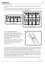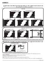
The placement of the screws, will be always at the distance B (except for ½ 6” 4x9
format modules, where the distance must be C), as shown in the image of the anex
(11-12). Minimum 4 screws per module must be situated.
(5).
5 .1.2.-
:
*Note
*Note
: In corrosive environments (salt spray), place nylon washers to insulate the
panel from the metal parts of the structure.
The aluminium frames of ATERSA’s photovoltaic modules have side channels that make
it easier to fix the module onto the profiles of the installation.
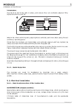
The Hook Fixing System is used to install the modules.This system can be installed on
standard structures , “U” type guide rail or guide insertion.
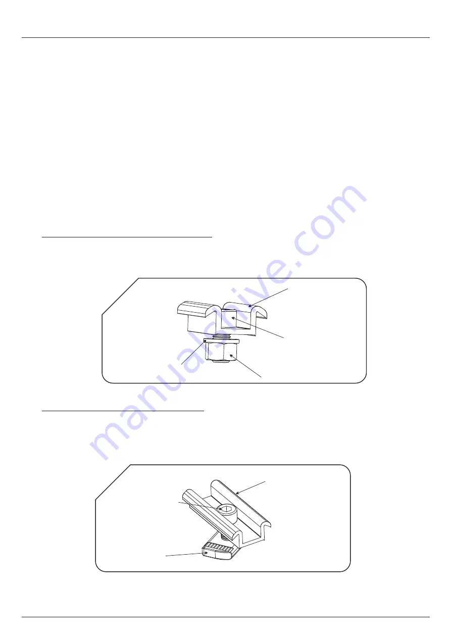
Fixing on standard structures is carried out using the dead-end clamp, the M8x20
serrated head Allen screw, flat washer and M8 nut. View image (4).
For this type of installation you need a 41x41mm or 41x21mm
"U" type perforated
profile. These elements do not come with the Hook Fixing System.
The assembled fixing should look like the picture shown in next figure:
: In corrosive environments (salt spray), place nylon washers to insulate the
panel from the metal parts of the structure.
Installation on standard structures
Installation on “U” type guide rail:
Hook Fixing System
M8 WHASER
M8 NUT
M8x20 ALLEN SCREW
DEAD-END CLAMP
4
M8x20 ALLEN SCREW
DEAD-END CLAMP
M8 GUIDE NUT
5
4
MODULE
Installation and User Manual
EN-MU-41 (4)-E


