TOTAL SECTION (External diameter):
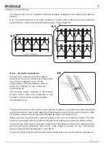
ELECTRICAL CONNECTION:
A direct cable connection can be made to the direct connect junction box using (max.
4mm ,AWG12) the cable termination spring clips in the junction box. In the manner
shown below, direct connection of cable sizes AWG14 and AWG12 can be
accommodated. The sealing grommet in the 2 rail assembly can accommodate
insulation diameters up to 8.0mm (0.31 inches). To ensure proper termination, cable
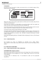
insulation should be stripped as shown in figure(7).
On multi-stranded conductors, it is recommended to use wire pins or at least to twist
the strand bundle to ensure all strands are captured in the spring clip. To open the
spring clip window for the cable, use the appropriate tool (see ATERSA product) or a
little screw, to insert vertically into the window as seen in figure 1.View image (8)
The cable can be inserted through the opened window into the clip (figure 2). Once the
cable is installed, lift the screw and the cable is fixed. Attention to the polarity of the
wires. Make sure that the cable is inside the clip and is fixed correctly, if the cable is not
installed correctly the juntion box will be deteriorated (electric arc).
After termination, tighten the grommet nut to compress the grommet around the
cable. Tightening torque for cable screw nut max. 1.5 Nm (0.34 lbf) depends on the
type of cable isolation. Hold cable screw joint with tool.
Connection boxes with integrated cable glands are used with 4mm² cable (AWG 12).
The tightening torque is 1.3
Nm (0.29 lbf). For this is recommended the use of a
slotted socket wrench with wrench size oh 13mm (0.51 inches). ,
. On models
72 and 60 cells, ATERSA provides wiring junction box installed. In these cases,
provided cables may not be modified, deleted, or be replaced by other.
rated 600/1000 V..
2
+0.2
The cable must fulfill the requirements to be used in photovoltaic systems
The cable used
by ATERSA in its modules is for outdoors use, UV resistent, double isolation layer, 1kV,
working temperature range -40ºC to 110ºC,
7
X= 11mm, 0.43 inches
8
Figure 1
Figure 2
6
Modules of 36 cells and ½ 36 cells
Modules of 36 cells and ½ 36 cells
MODULE
Installation and User Manual
EN-MU-41 (4)-E


