REGULATION SYSTEM
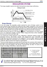
The charge regulation system is divided into two phases, deep charge and floating.
In the first phase, the regulation system permits the input of charge current to the
accumulators without interruption till reaching the final voltage charge point. Once reached
this point, the regulation system stops the charge and the control system goes to the second
phase, floating. When the final voltage charge point is reached, the battery has reached a
charge level next to 90% of its capacity. The charge will be completed in the next phase.
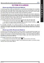
When the indicator which is in the drawing
lights, it indicates that it is in deep charge
cycle, not necessarily charging, but that "it can charge when there will be radiation",
consequently, it can be working at night.
The charge final voltage depends on the temperature, difference between charge and
discharge intensity, accumulator capacity and programmed value. Intensities and
temperature are directly measured by the equipment. The accumulator capacity and the
charge final voltage are values that can be modified in the Leo memory, even though it is
made with values by defect. See Programming paragraph.
The incremental resistance associated with the overload is the only term which variation in
accordance with the temperature products significant effects on the battery behaviour and,
the value of the final voltage of the charge is consequently corrected.
For small and medium Gel accumulators (Flo) or usual floating systems, as it is not
convenient to make deep charges, the final charge voltage is put equal to the
maximum floating voltage, it is to say:
Vc = Vf = 2.31 +(25-t) x 0.004
Deep Charge
The value of the
charge final voltage in PbA Mode, is obtained as follows:
CHARGE
PHASE
CHARGE
PHASE
FLOATING
PHASE
Floating Output Voltage
Final Voltage Charge
Minimum Floating Voltage
Maximum Floating Voltage
V
oltage
Time
Charge Cycle
Difference Int. => C/10
Vc =2.52 + (25-t) x 0.004 (volt./elem)
Difference Int. => C/20
Vc =2.50 + (25-t) x 0.004 (volt./elem)
Difference Int. => C/50
Vc =2.43 +(25-t) x 0.004 (volt./elem)
Vc = Charge final voltage
Difference Int. => C/100
Vc =2.41 +(25-t) x 0.004 (volt./elem)
Ic = Charge Intensity
Maximum floating voltage
Vf =2.31 +(25-t) x 0.004 (volt./elem)
T = temp. ºC.
Floating Range
0.05 V/element
C = Acucumulator Capacity
Maximum Floating Value
2,38 V/element
0.004 = Temperature Coefficient
Maximum Floating Value
Vn + 10 %
Floating output voltage
Vsf = 2.15
E
N
G
L
I
S
H
03
DIGITAL CHARGE REGULATOR
LEO1
MU-12-L

