MANUAL DATA ACQUISITION
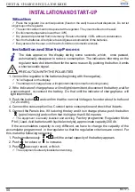
By pushing simultaneously
we make a test of components and obtain by
sequence a listing of some parameters as follows:
Remarks: The boards of programmed and handling voltages, you will observe that they
always refer to a 12 v. accumulator, independently from operation voltage of 12,24 or 48v.
Then the real value is multiplied by 1 (12v), by 2 (24v) or by 4 ( 48v).
+
A
A
Nº
Description
Value
1
Led nº1 (Deep charge Phase) lit.
2
Led nº2 (Floating Phase) lit.
3
Led nº3 (Consumption unplugging for low voltage) lit.
4
Led nº4 (Indicator of high voltage in batteries) lit.
5
Led nº5 (Indicator of low voltage in batteries) lit.
6
Display visualising 88.8
7
Version of the programming in ROM
8
Regulation, only floating (Mode FLO) or deep charge and floating
(Mode PbA)
9
Programmed Value: High voltage in battery Alarm
10
Programmed Value: Charge final voltage
11
Programmed Value: Maximum floating voltage
12
Programmed Value: Minimum floating voltage
13
Programmed Value: Output floating Voltage
14
Programmed Value: Consumption restart Voltage
15
Programmed Value: Alarm of low voltage in battery
16
Programmed Value: Consumption unplugging Voltage
17
Capacity of the accumulator system
18
Factor probing NTC
19
Handling Value: High voltage in battery Alarm
20
Handling Value: Charge final voltage
21
Handling Value: Maximum floating voltage
22
Handling Value: Minimum floating voltage
23
Handling Value: Output floating Voltage
24
Handling Value: Consumption restart Voltage
25
Handling Value: Alarm of low voltage in battery
26
Handling Value: Consumption unplugging Voltage
27
Counter of the historic operations
28
Counter of unplugging
29
Counter of floating
30
Counter of low voltage alarms
31
Conduction panel lines and subsequent cut (2 sec. approx.)
32
Consumption unplugging and subsequent restart (2 sec. approx.)
33
Display visualising 'Fin'
Function
Measure
Installation
I charge
Date
Hour
I unplugging
Data taken by
Battery voltage
DIGITAL CHARGE REGULATOR
LEO1
14
MU-12-L

