1.- SAFETY INFORMATION
Ø
Ø
Ø
Ø
Ø
Ø
Ø
Ø
Ø
Ø
Ø
2.- DESCRIPTION
MINO V2 series regulators provide suitable control for accumulator charging and
discharging operations in a photovoltaic system.
This regulation series is designed for low power systems for which no additional
instrumentation is required. It is a complete regulation system in itself and it is
characterised by its reliability and low consumption and cost. Only one dual-current (12 -
24 volts) version is available.
Built with SMD technology, this control system uses a staged charge algorithm
depending on the battery type, which allows a sophisticated charging of the accumulator
with temperature compensation.
To switch charge and consumption lines, a PWM charge regulation system with solid
state relays is used, which provides operation reliability and much longer duration than
electromechanical systems.
Handling batteries is dangerous. Protect your eyes. You should always have clean
water near you in case acid contact occurs.
Explosive gases might be released while charging batteries. Make sure the
premises are sufficiently ventilated. The ventilation system should at least have
one outlet on the upper areas of the room.
Use properly insulated tools. Do not place any metal objects near batteries, as they
might fall off and cause a short-circuit.
If exposed to sunlight, solar panels generate power constantly . Use insulated tools
during connection, as power cannot be turned off for the operation.
Do not install nor handle electrical components in rooms with flammable gas
hazard due to paint, varnish, or solvent presence.
Do not store flammable materials near the batteries or the regulator.
Short-circuit intensity in batteries can be very high and so cause a fire and even
blow the battery up.
Do not wear bracelets, chains, or other jewellery that might accidentally cause
undesirable and dangerous electrical contacts.
Do not work alone. Make sure there is always somebody around that can help if an
accident does occur.
Never smoke near a battery.
Recycle used batteries.
Operation instructions
3.- INSTALLATION AND COMMISSIONING
3.1.- General rules
3.2.- Location
3.3.- Steps
To ensure the accurate and lasting operation of the equipment, installation instructions
should be carefully observed.
This device
fulfill the requirement of CE marks regarding to the radio and
telecommunications emissions and immunity. For using it in telecommunications
systems with emitted frequencies higher than 230 MHZ. please contact with our
technical department.
Conductor selection is important in avoiding possible voltage sags that might cause the
system to operate incorrectly. As a reference, sags over 3% of the nominal voltage
should not be accepted in maximum intensity conditions.
To work out the necessary section, the following expression can be used:
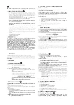
At the bottom of the regulator there is a connection bar; access to it is gained by pulling
up the cover. The connections are identified with the symbols of each line: Panel,
Battery, and Consumption respectively, polarity being indicated for each of them.
Prior to connection, check cable polarity. You are advised to connect the battery first,
then the consumption output, and finally the panel.
For the connection terminals, you can use up to 6 mm² section flexible cable or AWG-
type conductors nº. 10 with terminals, or up to 10 mm² unipolar cable or AWG-type
conductors nº 8.
The location must meet the following requirements.
Maximum room temperature under 50º.
It must be dry, should have no leaks or similar potential problems, and should not
be exposed to the elements.
Near the accumulators but free from gas emission.
Out of the reach of children and pets.
Conductor selection
Terminal identification.
Mains connection
Where 'L' is the line length in metres, 'Imax' stands for maximum intensity (in Amperes),
and “
“is the maximum voltage sag allowed in volts.
V
mm
Sección
³
MAX
I
2 L
× ×
V
×
56
)
(
2
Earth connection
The installation will operate correctly without an earth connection. If, for some reason,
the system requires an earth connection, connect ONLY one battery or consumption
point, either the positive or the negative one. If a choice is possible, then connect the
battery positive one only.
3.4.- Set up.
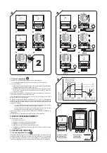
3.4.1.-Determine the operating mode
3.4.2.- Operating mode change
MINO V2 has 2 operating modes:
Mode 1: LeadAcid Battery (flooded).
Mode 2: Gel battery.
To determine the operating mode, please follow these steps:
Disconnect Panel Line, Consumption Line, and Battery Line.
Connect Battery only.
Count the number of slow flashes on the Battery LED (centre) to
determine the selected operating mode.
1 flash = mode 1 = LeadAcid Battery
2 flashes = mode 2 = Gel Battery
When the message is finished, the Panel LED (top) will flash once
1- Disconnect all connection terminals.
2- Connect consumption negative with panel negative temporarily.
3- Connect the battery.
4- The 3 LEDs will flash.
For mode 1 (Lead Acid Battery), remove the bridge or temporary connection after
the first flash.
For mode 2 (Gel Battery), remove the bridge or temporary connection after the
second flash.
5- Wait for 10 seconds to allow programming.
Check operating mode (3.4.1) to ensure the programming is successful.
1 -
2 -
3 -
Ø
Ø
Ø
4- Connect Consumption Line and panel line.
The default set up f the MINO V2 regulator is mode 1(LeadAcid Batteries). To change the
operation mode, follow these steps:
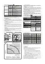
3.5.- Test Run.
1
2
3
4
5
- First, switch off Panel Line; next, switch off Battery Line.
Switch on
onsumption line.
- Switch Battery on.
The Battery LED (centre) will flash once or twice, as per the operation mode
selected, Mode 1 or Mode 2 respectively.
The consumption output is switched on and off simultaneously to check that the
consumption relay is working (the consumption element connected will be
switched on and off).
- After the flashing of the Battery LED (centre), the Panel LED will go on to indicate that
the Panel relay is working.
-
However, if the voltage is not 12.0V or 24.0V, the Battery LED (centre) will go on as many
times as number of volts (just units) and the Consumption LED (bottom) will go on as
many times as decimals in the battery voltage. For example:
-
On completion of the test, the regulator will start working automatically.
Ø
Ø
Ø
Ø
Ø
a consumption element (e.g. a bulb) on c
If the battery voltage is exactly 12.0V or 24.0V, all three LEDS will go on for one
second (adjustment voltage).
To complete the installation and get it running, connect the panel to the Panel Line.
Periodical checks:
Cleaning condition of panels.
Battery condition. Water level, if possible.
Rust on battery terminals.
Tightening of terminals after first six months.
Regulator ventilation grooves and battery housing grooves should remain open.
4.- MAINTENANCE INSTRUCTIONS
5.- OPERATIONALDESCRIPTION
Ø
Ø
Ø
Ø
Ø
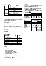
5.1.-Charge regulation curve.
MINO V2 manages a Staged Charge Cycle consisting of boost, equalization, absorption,
and float. The microcontroller's adaptive control algorithm allows it to learn installation
features and adapt to them. This optimises regulation management.
13'5V in the battery means the Battery LED (centre) will flash 3 times and the
Consumption LED (bottom) will flash 5 times. Digit 1 will be ignored.
27'4V in the battery means the Battery LED (centre) will flash 7 times and the
Consumption LED (bottom) will flash 4 times. Digit 2 will be ignored.


