6.3.- Operating Values
These values are modified by the uP programme on the basis of room temperature
and installation records. In 24V operations, voltage values on the table should be
multiplied by 2.
7.- WARRANTY
The warranty will not be applicable to:
The manufacturer shall not be held responsible for any personal damage or costs that
might result from the inadequate use of the product.
For the warranty service, please contact your dealer. Should this not be possible, please
contact the manufacturer directly.
Since ATERSA improve their products on an ongoing basis, the contents in this manual
are subjected to amendment without notice.
Ø
Ø
Ø
Ø
Ø
Ø
Damage caused by incorrect handling.
Ongoing use of charges over maximum nominal values.
Use in unsuitable room conditions (see Location section).
If equipment has been knocked or banged, dismantled, or repaired by
unauthorised service personnel.
Atmosphere electric shock, accidents, water, fire, and other circumstances out of
the manufacturer's control.
The warranty will cover any costs resulting from regular inspections, maintenance,
or shipping, neither for the labour nor for the regulator.
The TWO-YEARS warranty covers all manufacturing defects, parts and labour inclusive.
Pb-A
GEL
15,70 V
14,90 V
15,20 V
14,20 V
120 min.
120 min.
30 days
30 days
14,80 V
14,00 V
3 min
3 min
14,00 V
13,80 V
120 min.
120 min.
13,80 V
13,40 V
12,70 V
12,60 V
12,30 V
12,30 V
11,40 V
11,50 V
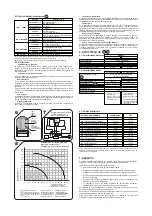
OPERATING VALUES
Maximum System Voltage.
VFQ = Equalisation Final Voltage.
TEQ = Equalisation Time (minutes).
Time between equalisations.
VFC =
Charge Voltage.
Final
TFC = End-of-charge Time.
VFA = Absorbtion Final Voltage.
TAB = Absorbtion Time.
VFL = Floating Voltage.
VRS = Reset Voltage.
LVR = Disconnection Reset Voltage.
LVD = Disconnection Voltage.
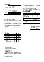
5.2.- LED Functions
5.3.- Protections
Note 1: 'Bright' and 'Faint' refer to the light intensity of the LED. If 'Bright', the LED will be fully lit up. If
'Faint', the LED will be fainter.
Note 2: During set up and test run, LED meanings are different.
Consumption short-circuits
Panel line short-circuits
The consumption output is equipped with a short-circuit protection system. On detection
of this event, the consumption outlet is turned off. Once the short-circuit is over, the
consumption output is automatically supplied with power.
The equipment has a specialised circuit that prevents panel line short-circuits from
damaging the regulator.
Power surge
Overcharge
Deep discharge
Polarity inversion
This protection type enables the absorption of induced power surges to a certain extent
but does not ensure protection if lightning directly strikes the installation.
An overcharge of the battery will imply a reduction of its electrolyte, and consecuently, it
will lead to its life shortening. This regulator protects the battery against overcharge by
switching off the panel input.
The regulation system prevents the battery from being deeply discharged by switching off
the consumption line.
Panel and battery connections are protected against polarity-inversion. If polarity
inversion occurs on the battery, the regulator switches off the panel input without causing
any breakdowns.
In photovoltaic systems power surges might occur for different reasons, such as storms.
The input line is protected against this event by means of varistors.
Opened Panel Relay.
STATUS
DESCRIPTION
BRIGHT
Not charging.
FAINT
Charging.
BLINKING
Floating.
LED 1 – PANEL
OFF
Not charging.
Blocking Diode Function
ON
Battery Charged. Overcharging (HVD) Protection.
Absorbtion Stage
BLINKING
Battery partially charged
LED 2 – BATTERY
OFF
Battery discharged
ON
Consumption Disconnected.
Deep Discharging (LVD) Protection.
BLINKING
Discharged Battery Alarm.
Consumption disconnected in 10 seconds.
OFF
Connected Consumption.
LED 2 Y LED 3
ON
High Temperature Alarm.
LED 3
CONSUMPTION
Temperature
Battery disconnection
Reverse Current Protection (Shunt Diode Function)
If internal temperature exceeds 70ºC (Ex. faulty ventilation, working continuously with
excessive intensity, ...), the relays will open to avoid electronic component damage. The
Battery and Consumption LEDs will remain on to report on this occurrence. Once the
suitable temperature level is reached again, control goes back to normal.
If the battery is disconnected by accident while in operation, consumption could be
supplied with excessively high voltage. To avoid this, MINO V2 switches shuts the
system off automatically. To resume operation, connect the battery.
Through electronic circuitry with Mosfets, MINO V2 prevents the battery from being
discharged through the panel at night. The circuitry provides better performance than
the use of standard blocking or shunt diodes.
6.-
6.1.-
TECHNICALDATA.
Electrical features
Nominal Voltage
6.2.-
Physical
features
MODEL
MINO V2 12/24V 15
MINO V2 12/24V 30
12/24V (automatic)
Standard Consumption
6 mA
Charge intensity range
0 - 12 A
0 - 16 A
No leak-tight box
Leak-tight box
0 - 21 A
0 - 28 A
Consumption intensity range
Maximum Cable Section
Weight (approximate)
250 g.
1kg.
Dimensions
140 x 116 x 30 mm.
150 x 240 x 76 mm.
Watertight Grade
UV protection
Others features
Painted box
YES
IP-20
IP-67
RAL- 1013
RAL- 7035
Working temperature range
-10º C to + 40º C
"
"
"
"
Polycarbonatebox
withtransparentcover
FireprotectionUI94V2
BlowprotectionIK08
Threeplasticcable
glandsIP-68inorderto
enablealeaktight
cablingofthebox
"
"
Auto extinguishable
cover
Aluminum base with
c a t a p h o r e s i c
treatment in its frontal
face
6 mm² flexible wire terminal
10 mm² mono-pole wire
Max. outer Ø cable:14 mm.


