OPTIMUM GS MODULES INSTALLATION MANUAL
Page 13
Aplicaciones Técnicas de la Energía S.L. (ATERSA)
www.atersa.com – atersa@elecnor.com
Madrid (Spain) +34 915 178 452 - Valencia (Spain) +34 961 038 430
6.2.
Electrical Connections
6.2.1.
Equipment Grounding
•
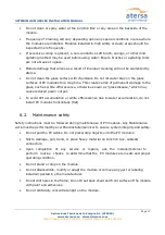
To avoid the risk of electrical shock or fire, the
module frame should be grounded before the
electrical connection of the modules is
operated.
1. Stainless steel M5 - 304 bolt
2. Stainless steel M5 - 304 flat washer
3. Stainless steel M5 - 304 nut
•
The tightening torque
should be 2.1±0.1 Nm
•
A good connection between the grounding hardware is essential for an effective
ground. The anodization on a module frame provides a coating to minimize the
corrosion due to weather and it acts as a barrier that reduces the effectiveness of the
grounding connection. For an adequate ground, the grounding hardware should
penetrate the anodization layer.
Use the marked 5.1 mm grounding holes (5.1mm) to
ground the anodized frame.
•
10-12 AWG exposed copper wire is recommended as Ground wire.
•
The fastening system must be spliced with a cable that has a minimum diameter of
2.5mm
2
•
The copper wire cannot be attached directly to the aluminum.
6.2.2.
Bypass Diodes
Partial shading of an individual module can cause a reverse voltage across the shaded GES
SOLAR module. Current is then forced through the shaded area by the other modules.
When a bypass diode is wired in parallel with the series string, the forced current will flow
through the diode and bypass the shaded GS SOLAR module, thereby minimizing module
heating and array current losses.
In system utilizing a battery, blocking diodes are typically placed between the battery and the
GS module output to prevent battery discharge at night.
Diodes that are used as blocking diodes must: Have a Rated Average Forward Current [IF(AV)]
above
maximum system current at highest module operating temperature. Have a Rated
Repetitive Peak Reverse Voltage [VRRM]
above
maximum system voltage at lowest module
operating temperature.


