background image


OPTIMUM GS MODULES INSTALLATION MANUAL


Page 3 

Aplicaciones Técnicas de la Energía S.L. (ATERSA) 

www.atersa.com – atersa@elecnor.com   

Madrid (Spain) +34 915 178 452 - Valencia (Spain) +34 961 038 430 


1.


Introduction 

Thank you for choosing Atersa 

photovoltaic (

PV) module. It is the great honor to provide you 

our PV modules. This manual contains information regarding the installation and safe handling 

of  Atersa.


The  word  "module"  or  "PV  module"  used  in  this  manual  refers  to  one  or  more 

GSE-Series solar modules. Installers must read and understand the guide before installation. 

Any  questions,  please  contact  our  sales  department  for  further  explanations.  The  installer 

should conform to all safety precautions in the guide and local codes when installing a module.   

Before  installing  a  solar  photovoltaic  system,  installers  should  become  familiar  with  the 

mechanical and electrical requirement for such a system. Keep this guide in a safe place for 

future reference (care and maintenance) and in case of sale or disposal of the modules. 


2.


Disclaimer of Liability   

Because the use of this manual and the conditions or methods of installation, operation, use 

and maintenance of photovoltaic (PV) product are beyond Atersa’s control, Atersa does not 

accept responsibility and expressly disclaims liability for loss, damage, or expense arising out 

of or in any way connected with such installation, operation, use or maintenance.   

No responsibility is assumed by Atersa for any infringement of patents or other rights of third 

parties, which may result from use of the PV product. No license is granted by implication or 

otherwise under any patent or patent rights.     

The information in this manual is based on Atersa’s knowledge and experience and is believed 

to be reliable; but such information including product specification (without limitations) and 

suggestions do not constitute a warranty, expresses or implied. Atersa reserve the right to 

change the manual, the PV produce, the specifications, or product information sheets without 

prior notice.   

Warning: 

Read  this  instruction  sheet  in  its  entirety  before  installing,  wiring,  or 

using  this  product  in  any  way.  Failure  to  comply  with  these  instructions  will 

invalidate the Atersa Warranty for PV Modules. 


In summary, the Limited Warranties do not apply to any of the following: 

PV  modules  which  in  Atersa's  absolute  judgment  have  been  subjected  to:  misuse,  abuse, 

neglect or accident; alteration, improper installation, application or removal (including but not 

limited  to  installation,  application  or  removal  by  any  party  other  than  a  Atersa  authorized 

dealer);  non-observance  of  Atersa's  installation,  users  and/or  maintenance  instructions; 

repair  or  modifications  by  someone  other  than  an  approved  service  technician  of  Atersa; 

power  failure  surges,  lightning,  flood,  fire,  accidental  breakage  or  other  events  outside 

Atersa's control. 


Summary of Contents for OPTIMUM A-235P GS

Page 1: ...ATION MANUAL Page 1 Aplicaciones T cnicas de la Energ a S L ATERSA www atersa com atersa elecnor com Madrid Spain 34 915 178 452 Valencia Spain 34 961 038 430 OPTIMUM GS Modules Installation Manual Re...

Page 2: ...ty 4 Precaution for unpacking handling storage 5 Warning 6 Installation 6 1 Mechanical Installation 6 1 1 Bolting method 6 1 2 Clamping method 6 2 Electrical Connections 6 2 1 Equipment Grounding 6 2...

Page 3: ...f or in any way connected with such installation operation use or maintenance No responsibility is assumed by Atersa for any infringement of patents or other rights of third parties which may result f...

Page 4: ...shall comply with national regional and local codes laws and standards PV modules should be installed and maintained by qualified personnel Only installation service personnel should have access to t...

Page 5: ...s to avoid injury by a slipping module cuts by the edge of a frame etc Do not leave the module unsupported or unsecured prior to installation For example wind can cause a module which is leaning again...

Page 6: ...lation of PV modules Use module for its intended function only Be sure that all other system components are compatible and they do not subject the module to mechanical or electrical hazards Do not tou...

Page 7: ...the southern hemisphere The assembly is to be mounted over a fire resistant roof covering rated for the application The roof slope should be less than 5 in ft less than 22 62 to maintain fire class r...

Page 8: ...not accessible to children or small animals to ensure personal safety and to prevent PV module from damage The junction box shall be in the uppermost position to minimize the ingress of water Clearan...

Page 9: ...oints The hardware required to mount the module is given below Stainless steel M8 304 bolt Stainless steel M8 304 washer Stainless steel M8 304 nut We recommend using a torque wrench for installation...

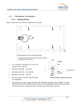
Page 10: ...lecnor com Madrid Spain 34 915 178 452 Valencia Spain 34 961 038 430 6 1 2 Clamping method For the clamping method is recommended use clamps with figure s sizes The hardware used is the same as boltin...

Page 11: ...OPTIMUM GS MODULES INSTALLATION MANUAL Page 11 Aplicaciones T cnicas de la Energ a S L ATERSA www atersa com atersa elecnor com Madrid Spain 34 915 178 452 Valencia Spain 34 961 038 430...

Page 12: ...OPTIMUM GS MODULES INSTALLATION MANUAL Page 12 Aplicaciones T cnicas de la Energ a S L ATERSA www atersa com atersa elecnor com Madrid Spain 34 915 178 452 Valencia Spain 34 961 038 430...

Page 13: ...mm grounding holes 5 1mm to ground the anodized frame 10 12 AWG exposed copper wire is recommended as Ground wire The fastening system must be spliced with a cable that has a minimum diameter of 2 5m...

Page 14: ...ed in series with each module or string of modules Match the polarities of cables and terminals when making the connections failure to do so may result in damage to the module Connecting modules in re...

Page 15: ...or the corresponding equipment to which the module are connected A cable with an adequate section for the conduction of the total current generated by the modules should be used In all case the conduc...

Page 16: ...Always wear rubber gloves for electrical insulation while maintaining washing or cleaning modules Appropriate electrically insulating Personal Protective Equipment PPE must be worn during any cleaning...

Page 17: ...permanent damage to the glass such as white efflorescence otherwise known as glass disease which may cause reduced power output To avoid dirt accumulation or white efflorescence due to water accumulat...

Page 18: ...rsa com atersa elecnor com Madrid Spain 34 915 178 452 Valencia Spain 34 961 038 430 9 Checklists All fastenings are tight and secure and free of corrosion All cable connections are secure tight clean...

Page 19: ...STC Irradiance of 1000 W m2 AM1 5 spectrum and a cell temperature of 25 C The tolerance of Electrical Characteristics is less than 10 under Standard Test Conditions 2 1 Polycrystalline module Module A...

Page 20: ...ort circuit current A 8 54 8 71 8 84 8 90 8 97 9 05 9 10 9 13 Max power point current A 8 04 8 17 8 28 8 35 8 42 8 49 8 56 8 04 Efficiency 14 5 14 8 15 1 15 4 15 7 16 0 16 3 14 5 2 2 Monocrystalline m...

Page 21: ...9 08 Max power point current A 8 00 8 04 8 11 8 20 8 25 8 34 8 42 8 51 Efficiency 14 4 14 8 15 1 15 4 15 7 16 0 16 3 16 6 Notes Maximum System Voltage 1000V Nominal Operating Cell Temp NOCT 46 2 C Te...

Reviews: