www.atestgaz.pl
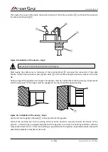
Then lower the cover of the cable connector, disconnect the cable connector ④ and thread the cable via
the cable inlet (bushing)⑤.
Figure 9: Installation of the device – step 3
Secure ends of stranded conductors with sleeves.
After having the cable cores to terminals of the terminal block ⑥ reconnect the connector of the cable
bundle, reinstall the connector cover, tighten bolts ② and lock the cable gland home by means of the tool
N2.
Finally, suspend the signaller on a hanger. The signaller must be installed from the top moving it downwards
and the upper part of the hanger must be engaged in the top deck of the device housing.
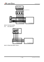
Figure 10: Installation of the device – step 4
Use the N1 tool to tighten the bolt ⑦ to lock position of the signaller.
Connect the earthing line to the earthing terminal of the device to securely connect the device to the
ground – a terminal lug is supplied together with the signaller to connect the earthing conductor with the
cross-section from 0.5 to 2.0 mm
2
. No earthing is required when the signaller is operated outside areas with
potentially explosive atmospheres (Ex zone).
s. 16|23
User Manual: POD-037-ENG R06
⑦
③
④
⑥
⑤


