www.atestgaz.pl
Table of contents
1 General information............................................................................................................................................. 6
1.1 Main features of the device......................................................................................................................................6
1.2 Explosion-proof protection.......................................................................................................................................7
1.3 Cable glands..............................................................................................................................................................7
1.4 Cables........................................................................................................................................................................7
2 Safety.................................................................................................................................................................. 7
3 Device design....................................................................................................................................................... 7
4 Input-output interfaces........................................................................................................................................ 8
4.1 Electrical interface....................................................................................................................................................8
5 User interface...................................................................................................................................................... 9
5.1 LTT2...........................................................................................................................................................................9
5.2 LTT4.........................................................................................................................................................................10
5.3 The field of the signaller own states.......................................................................................................................10
6 System architectures.......................................................................................................................................... 11
6.1 Sigma.......................................................................................................................................................................11
6.2 Modbus...................................................................................................................................................................12
7 PW-091-M-X / PW-089-M-X device with Modbus interface.................................................................................12
7.1 Device control.........................................................................................................................................................12
7.2 Configuration..........................................................................................................................................................13
8 Lifetime cycle..................................................................................................................................................... 13
8.1 Transportation.........................................................................................................................................................13
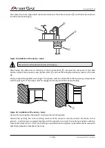
8.2 Installation..............................................................................................................................................................13
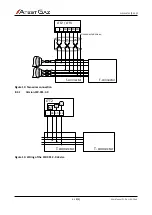
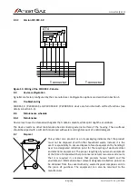
8.3 Connections............................................................................................................................................................17
8.4 Device configuration...............................................................................................................................................19
8.5 Troubleshooting......................................................................................................................................................19
8.6 Maintenance schedule............................................................................................................................................19
8.7 Disposal...................................................................................................................................................................19
9 Technical specification........................................................................................................................................ 20
10 Product marking............................................................................................................................................... 21
10.1 LTT2 Warning LED Tower with Sounder................................................................................................................21
10.2 LTT4 Warning LED Tower with Sounder................................................................................................................22
11 Appendices...................................................................................................................................................... 23
List of Tables
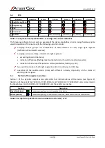
Table 1: Optical indicators status notation................................................................................................................ 3
Table 2: Electric connections description – PW-091-S-X, PW-091-M-X, PW-089-S-X, PW-089-M-X...............................9
Table 3: Electric connections description – PW-091-C-X, PW-089-C-X.........................................................................9
Table 4: Configuration example PW-091-X – meaning of the device indications.........................................................9
Table 5: Configuration example PW-089-X – meaning of the device indications........................................................10
Table 6: Description of pilot LED for status indication of the LTT2 / LTT4..................................................................10
Table 7: List of tools necessary for installation of the signaller.................................................................................14
Table 8: Technical specification............................................................................................................................... 20
Table 9: Configuration of PW-091-S-X, PW-091-M-X version....................................................................................21
Table 10: Configuration of PW-091-C-X version........................................................................................................22
Table 11: Configuration of PW-091-S-X, PW-091-M-X version...................................................................................22
Table 12: Configuration of PW-089-C-X version........................................................................................................23
s. 4|23
User Manual: POD-037-ENG R06


