www.atestgaz.pl
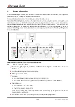
Installer friendly. Mistakes and errors in connections does not result in device damage.
Device can also easily communicate a proper operation of the connected (controlling) devices,
including connection / control lines (type PW-091-S-X / PW-089-S-X and PW-091-M-X / PW-089-
M-X).
1.2
Explosion-proof protection
Details about explosion protection are provided in the Section 9.
1.3
Cable glands
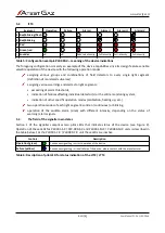
The cable gland is replaceable element. To select spare please obey the following rules:
type of explosion protection Ex db IIC Gb or Ex eb IIC Gb,
operating temperature range (see Table 8),
appropriate IP degree (IP code) – no worse than the device (see Table 8),
appropriate mounting thread – see Table 8.
Details see Chapter 9.
1.3.1
Replacement of cable gland
To replace/screw the cable gland:
remove the gland from device (if it is screwed in),
screw in a new cable gland.
1.4
Cables
Thermal resistance of cables must comply requirements set forth in Table 8.
2
Safety
All activities related to connecting signaller must be carried out while control unit's power
supply is off.
Prior to opening the device enclosure disconnect all sources of power voltage.
Do never unscrew bolts on the side wall of the enclosure. Loosening of specially marked
bolts leads to loss of the enclosure tightness and warranty for the device is made null and
void (see Figure 8).
3
Device design
Dimension and enclosure of signaller shown below.
s. 7|23
User Manual: POD-037-ENG R06


