www.atestgaz.pl
No.
Name
Pin
Description
I
Power Supply
Signaller power supply port. Parameters – see section 9
-
Negative
+
Positive
II
SBUS
System communication port, see section 9. Used for data exchange between devices in Sigma
Gas system and for signaller with Modbus interface configuration (PW-091-M-X / PW-089-M-X)
SA
Signal line A
SB
Signal line B
III
ExBUS
System communication port, see section 9. Used for data exchange between external systems
(e.g.: SCADA, PLC) and for signaller with Modbus interface configuration (PW-091-M-X / PW-
089-M-X)
EA
Signal line A
EB
Signal line B
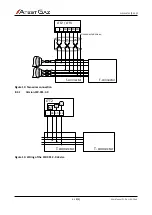
Table 2: Electric connections description – PW-091-S-X, PW-091-M-X, PW-089-S-X, PW-089-M-X
No.
Name
Pin
Description
1
-
Negative
2
A+
Control and signalling input of the acoustic signaller.
Activation of the acoustic signaller. Applying the supply voltage to the pin activates the acoustic
signalling
3
1+
Control and signalling input of the 1 LED segment. Applying the supply voltage to the pin
activates the optical signalling
4
2+
Control and signalling input of the 2 LED segment. Applying the supply voltage to the pin
activates the optical signalling
5
3+
Control and signalling input of the 3 LED segment. Applying the supply voltage to the pin
activates the optical signalling (only for PW-089-C)
6
4+
Control and signalling input of the 4 LED segment. Applying the supply voltage to the pin
activates the optical signalling (only for PW-089-C)
Table 3: Electric connections description – PW-091-C-X, PW-089-C-X
5
User interface
5.1
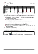
LTT2
Segment
Operation
Failure
Alarm I
Alarm II
2
Red/blinking/flash
1
Green/red
-
Sounder
off
off
Reduced intensity
Full intensity
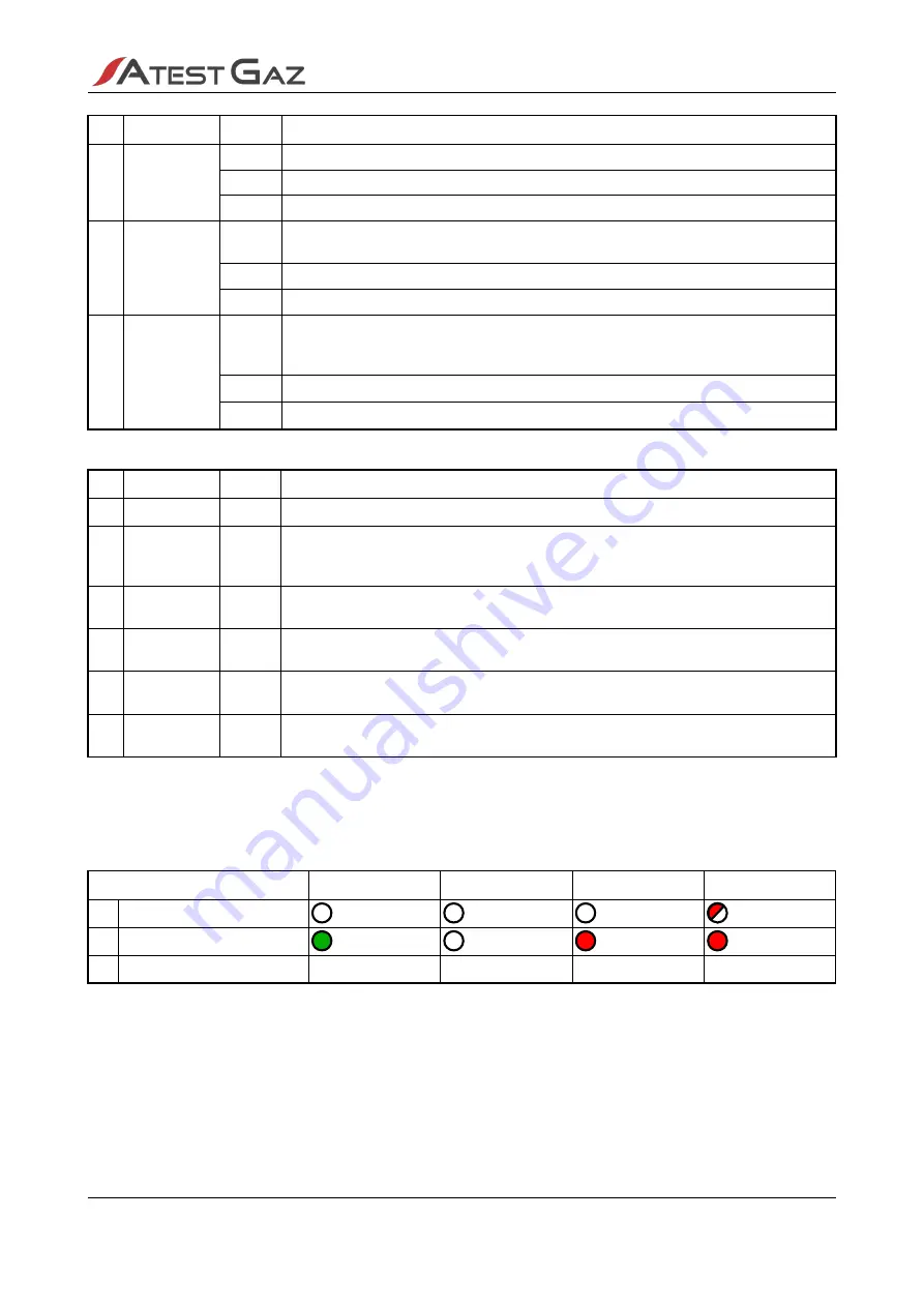
Table 4: Configuration example PW-091-X – meaning of the device indications
s. 9|23
User Manual: POD-037-ENG R06


