background image


www.atestgaz.pl

7.7

Maintenance schedule 

Each user must be aware of the fact that operation of any gas monitoring system leads to inevitable ageing

of equipment, in particular gas sensors, due to detrimental impact of environmental factors. Therefore the
systems must undergo regular and scheduled maintenance.
Maintenance operations shall include:

calibration of gas detectors, 
replacements of fast-wearing parts, 
scheduled inspections.

7.7.1

Calibration

Gas sensor incorporated into the device is a component that subject to ageing due to environmental

factors, which inevitably leads to deterioration of its sensitivity. 
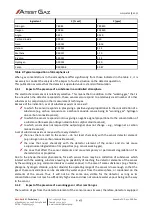
To compensate the deterioration effect the gas detectors must be calibrated on the regular basis (calibration
frequency is specified in the Calibration Certificate – see Table 5) by authorized personnel of the equipment

manufacturer. The calibration procedure can be carried out in several manners: 

dismounting of the gas detector to send it to the manufacturer for calibration, 
removing   only   sensor   plates   to   send   them   to   the   manufacturer   for   calibration   (see   Section
7.7.2.1),
sending a request to authorized service team of the manufacturer to come and calibrate the

detectors on site.

7.7.2

Replacement of fast wearing parts 

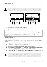
Please refer to Table 6 for the recommended lifetime and replacement schedule of fast wearing parts.
7.7.2.1 Replacement of a sensor plate
Operation of gas detector leads to natural deterioration of metrological parameters of gas sensors. That
effect can be compensated by regular and scheduled adjustment of the detector indication up to the

moment when the sensor is completely exhausted and must be replaced. It is assumed that replacement of
a gas sensor should take place when its sensitivity drops below 50% of the initial one. 
Replacement of a sole sensor is infeasible since it sits on a base plate (sensor plate) and must be replaced

together with its plate – see Table 6.
To replace the sensor plate proceed in the following way:

switch off the power voltage for the gas detector, 
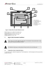
open the device housing, 
replace the sensor plate (see Figure 1),
close the housing, 
switch on the power voltage for the gas detector. 

7.7.3

Test / simulation

Tests of the gas monitoring systems are necessary to make sure that the gas monitoring system is in sound
operating condition. Please contact the equipment manufacturer in case of any irregular response of gas

detectors. 
The following tests can be distinguished: 

s. 16|20

User Manual: POD-046-ENG R01

Summary of Contents for Teta EcoN

Page 1: ...POD 046 ENG R01 User Manual Gas Detector Teta EcoWent Teta EcoN Product code PW 105 CO PW 111 NO2...

Page 2: ...Monitoring Detection and Reduction of gas hazards For more details please visit our website www atestgaz pl Atest Gaz A M Pachole sp j ul Spokojna 3 44 109 Gliwice Poland tel 48 32 238 87 94 fax 48 3...

Page 3: ...ces in not allowed Engineering of a gas detection system for any specific facilities to be safeguarded may need consideration of other requirements during the entire lifetime of the product Use of una...

Page 4: ...18 8 Technical specification 19 9 List of fast wearing parts 19 10 List of accessories 20 11 Marking codes of products 20 12 Appendices 20 List of Tables Table 1 Electric connections 9 Table 2 Indica...

Page 5: ...sholds Indication of detector faults 1 2 Operation principle Gas detectors are crucial components of any system for gas detection They are designed for periodical measurements of gas concentration in...

Page 6: ...indications preferably under daily basis periodical inspection and calibration see Section 7 7 1 1 2 2 Alarm 1 threshold 1 Alarm 2 threshold 2 It is the device status when only slight concentrations o...

Page 7: ...edure takes about two minutes and the detector starts normal operation 2 Safety Do never install gas detectors at locations exposed to direct effect of water moisture or direct sunlight When defects a...

Page 8: ...entional painting or paint splashing Before use of silicon or silicon based materials paints adhesives sealant etc make sure that the device is properly secured against unintentional coating 3 Device...

Page 9: ...Ds are located on the side wall of the device housing see Figures 1 and 2 Figure 2 User interface Table 2 summarizes how status of the gas detector is indicated by means of individual LEDs Detailed de...

Page 10: ...g it is just enough to approach a permanent magnet to a specific location on the housing this location is shown in Figure 1 Depending on the operation mode of the detector the following details are di...

Page 11: ...hat type If the original package or another protecting means e g corks is unavailable the conveyed equipment must be secured against shocks vibrations or moisture by means of adequate methods and mate...

Page 12: ...Figure 1 Drilling of mounting holes in walls or other permanent structures is easier with use of a drilling pattern attached to the device package 7 3 1 Electric network The electric network must be d...

Page 13: ...all devices carry out the following operations assign addresses to all detectors see details in section 7 5 1 select the operation mode s see details in section 7 5 2 configure the control unit see Us...

Page 14: ...lected address is not confirmed and stored the old address remains intact and after 15 seconds the detector quits the mode of address assignment The default address is 99 7 5 2 Operation modes of gas...

Page 15: ...e operation mode see Section 7 5 2 Gas detector is coupled with the Teta MiniDet device Defect of Teta MiniDet Gas Detector Improper setting for the operation mode see Section 7 5 2 Improper connectio...

Page 16: ...f the manufacturer to come and calibrate the detectors on site 7 7 2 Replacement of fast wearing parts Please refer to Table 6 for the recommended lifetime and replacement schedule of fast wearing par...

Page 17: ...out any delay When the detector under test is coupled with the Teta MiniDet detectors the test gas LPG must be also supplied to the second device Correct execution of the test needs application of a c...

Page 18: ...magnet to gas detector or initiation of alarm simulations 7 7 4 Maintenance Gas detectors should be cleaned only by wiping its housing with a soft damp cloth Cleaning agents containing solvents white...

Page 19: ...sed into the installation pipe diameter of the pipe 16 mm Glands multiband diameter of wire 3 5 12 mm Acceptable cable cores 0 2 2 5 mm2 wire cores 0 2 2 5 mm2 stranded cores Enclosure material ABS We...

Page 20: ...ized reference gas nitrogen dioxide NO2 with concentration of 10 ppm Table 7 List of accessories 11 Marking codes of products Product code Device name PW 105 CO Gas Detector Teta EcoWent PW 111 NO2 Ga...

Page 21: ...ng to electromagnetic compatibility EN 50270 2006 This declaration of conformity is issued under the sole responsibility of the manufacturer Purpose and scope of use product is intended for use in gas...

Page 22: ...atmosphere 4 3 1 2 Impact of the presence of a working gas or other reaction gas 4 3 1 3 Effect of oxygen concentration value 5 3 2 Influence of temperature 5 3 3 Influence of moisture 5 3 4 Influenc...

Page 23: ...reference electrode is used 5 It has a constant potential that is not dependent on the concentration of the measured gas Owing to electrode reactions electrons are generated whose orderly flow electri...

Page 24: ...ith the provisions in the User s Manual 3 1 Composition of the controlled atmosphere It is assumed that the standard composition of the atmosphere is a mixture of gases with the proportions indicated...

Page 25: ...signal does not change e g nitrogen at a carbon monoxide sensor A set of substances exists or may exist for every detector the ones that are inert to the sensor do not react chemically with the sensor...

Page 26: ...ed atmosphere is within the rated range of the detector operation it does not affect the reading However sudden abrupt changes of humidity in the measured atmosphere can cause momentary appearance of...

Page 27: ...rocess e g weather conditions safety potential hazard generated by the mixture criterion B These both criteria have an impact on the final cost of the calibration services and level of competence requ...

Page 28: ...of flammable components 60 LEL concentration of toxic components NDSCh2 oxygen concentration 25 vol tank 3 dm3 water capacity and p 70 atm specified liquid chemical compounds e g glycerol 1 2 propaned...

Page 29: ......

Page 30: ......

Page 31: ......

Page 32: ......

Reviews: