www.atestgaz.pl
4
Input-output interfaces
4.1
Electric interface
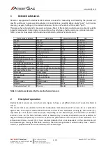
Locations and arrangement of terminal blocks is shown on Figure 1.
Port designation
Name
Terminal
Description
X1
TETA BUS
Teta Bus port. Parameters – see section 8
Supply / data transmission line
X2
Port for connection of the Teta MiniDet Gas Detector
M+
1
Positive
MS
2
Signal line
M-
3
Negative
Table 1: Electric connections
5
User interface
5.1
Indication of the device status
Gas detectors are provided with three LED indicators to show status of the device. These LEDs are located
on the side wall of the device housing (see Figures 1 and 2).
Figure 2: User interface
Table 2 summarizes how status of the gas detector is indicated by means of individual LEDs. Detailed
description of possible operation status is provided in Section 1.2.
LED
indicator
LED indication
Operation mode
CO / NO
2
Regular operation of the detector, gas concentration below the established thresholds
Alarm 1
Alarm 2
Alarm 3
Failure of the measuring path for CO or NO
2
, incorrect connection
Warm-up of the measuring path for CO or NO
2
LPG
Regular operation of the detector, gas concentration below the established thresholds
Alarm 1
2
G – green, Y – yellow, R – red.
s. 9|20
User Manual: POD-046-ENG R01
G
R
R R
R R R
Y Y Y Y
G Y R
G
R


