www.atestgaz.pl
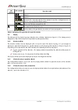
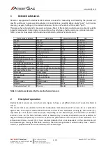
LED
indicator
LED indication
Operation mode
Alarm 2
Alarm 3
Failure of the measuring path for LPG, incorrect connection, configuration error or
defect of the coupled Teta MiniDet detector
Warm-up of the measuring path for LPG
No requests from the Control Unit
Internal defect of the gas detector (no relation to the measuring paths)
Table 2: Indication of the gas detector operation modes
5.2
Display
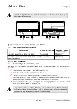
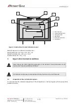
The side wall of the device housing comprises also a display module (see Figure 1). The display panel is
designed to show information that is explained in subsequent sections.
5.2.1
Detector address
The detector address can be displayed with no need to open the device housing, it is just enough to
approach a permanent magnet to a specific location on the housing (this location is shown in Figure 1).
Depending on the operation mode of the detector the following details are displayed:
regular operation of the detector – the display presents sequentially the detector address (Ad), its
setting and tE,
failure or warm-up – the sequence of address (Ad) and setting.
The device address can be also displayed by means of configuration buttons.
5.2.2
Information about operation details
The configuration buttons can be also used to display details related to operation modes of the detector
(HE) - see more in Section 7.5.2.
5.2.3
Information about tests /simulations
The configuration buttons can be also used to display details related to completed tests/simulations of the
detector – see more in Section 7.7.3.
s. 10|20
User Manual: POD-046-ENG R01
R R
R R R
Y Y Y Y
Y
Y Y Y Y
G Y R


