www.atestgaz.pl
6
System architectures
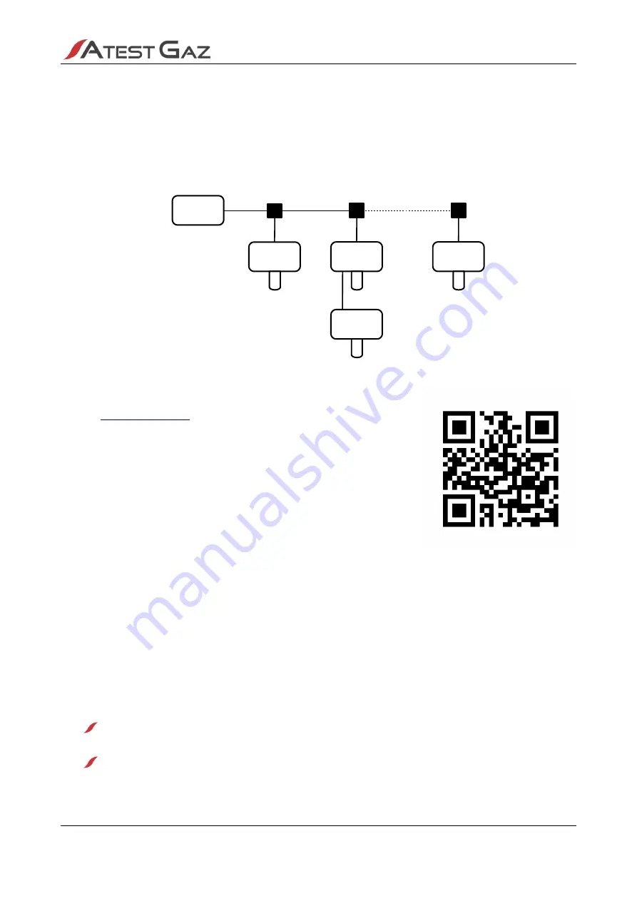
The gas monitoring systems can be made up of independent gas detector Teta EcoWent or Teta EcoN or
coupled and collaborating pairs of detectors (Teta EcoWent with Teta MiniDet).
6.1
Data bus architecture
In this system gas detectors are connected to the bus via T-connectors S2.
Figure 3: Arrangement of gas detectors according to the data bus architecture
Detailed schematic diagrams in an editable format can be found on our
website
7
Lifetime cycle
7.1
Transportation
The device can be shipped in the same way as new equipment of that type. If the original package or
another protecting means (e.g. corks) is unavailable the conveyed equipment must be secured against
shocks, vibrations or moisture by means of adequate methods and material at the own responsibility of the
sender.
The device can be conveyed under environmental conditions as described in Table 5.
7.2
Installation
7.2.1
Deployment of gas detectors
Deployment of gas detectors must be determined by the system designed with consideration to the
following rules:
installation of CO detectors is recommended at the height of upper respiratory airways, i.e. circa
1.2 to 1.7 above the floor level,
NO
2
detectors should be installed at about 30 cm above the floor,
s. 11|20
User Manual: POD-046-ENG R01
Teta
MOD Control 1
Teta
EcoN
Teta
EcoWent
Teta
MiniDet
Teta
EcoWent


