www.atestgaz.pl
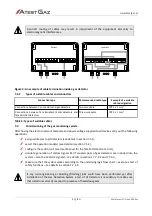
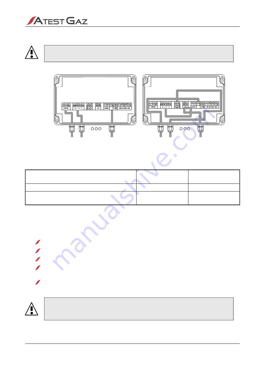
Incorrect routing of cables may result in impairment of the equipment immunity to
electromagnetic interferences.
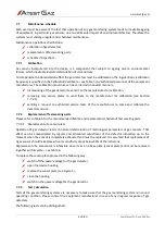
Figure 4: An example of cable termination inside a gas detector
7.3.2
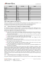
Types of suitable cables and conductors
Connection type
Recommended cable type
Example of a suitable
cable designation
Connections between T-connectors and gas detectors
Two-core cable
YDY 2 x 1 mm
2
Connections between Teta EcoWent /EcoN detectors and
Teta MiniDet detectors
Three-core cable
YDY 3 x 1 mm
2
Table 3: Types of suitable cables
7.4
Commissioning of the gas monitoring system
After having the electric network complete and power voltage supplied to all devices carry out the following
operations:
assign addresses to all detectors (see details in section 7.5.1),
select the operation mode(s) (see details in section 7.5.2),
configure the control unit (see User Manual for the Teta MOD Control 1 Unit),
simulate generation of alarms signals S1 (if coupled pairs of gas detectors are included into the
system – also the S2 alarm signals) – see details in sections 7.7.3.2 and 7.7.3.3,
make sure that the system works according to the underlying logic flow chart – execute a test of
safety functions – see details in section 7.7.3.4.
If any civil engineering or building (finishing) jobs could have been performed yet after
installation of the Gas Detection System a test of all detectors is mandatory to make sure
that detectors correctly respond to presence of hazardous gases.
s. 13|20
User Manual: POD-046-ENG R01
Incorrect
Correct


