background image


15 

® Copyright ATH-Heinl GmbH & Co. KG, 2013, All rights reserved. / Misprint and technical changes reserved


/ Issue: 04/2012


7.2 Service-calibration of wheel balancer ATH 1200 (Operation in both modes) 


Fort he calibration must be clamped a 
wheel with steel rim 

≥ 15 

inches (CAR-

mode)  resp.  

≥ 22,5 

inchesl (TRUCK-

mode)  and the wheel parameters 
must be entered. 
 
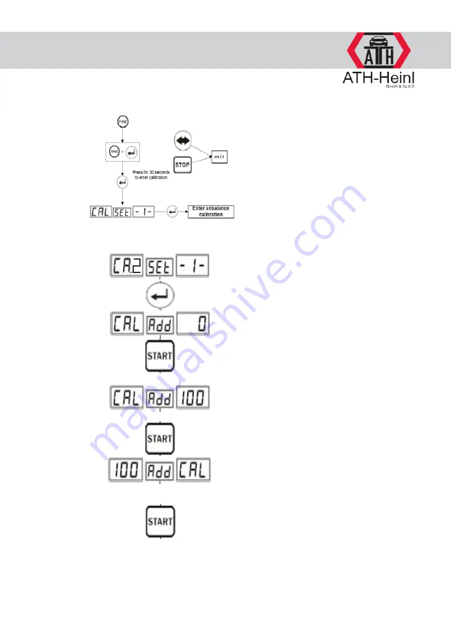
With adjacent key combination will be 
called the standard calibration: 

Press button FINE, then additionally 
ENTER, release FINE, release 

ENTER only after the display „CAL 1“ 

appears.  

With the following key combination can 
now be called the service calibration

Press ENTER, then FINE, hold both 

keys until „CA.2“ appears in the 

display, then release first ENTER and 
then FINE.  

 
After pressing the button ENTER 

appears „CAL

-Add-

0“ in the display.


By pressing the button START the 
balancing process for the calibration 
will be started. 
 
After the balancing process appears in 
the display 

„CAL

-Add-

100“. Turn the 

wheel until all LED´s of the display 
unbalance illuminate and fix the 100g 
weight at the position 12 o´clock 
outside.  
 
By pressing the button START the 
balancing process for the calibration 
will be started newly. 
 
After the balancing process appears 

„100

-Add-

CAL“ in the display. 

Remove 

the 100 g weight outside. Turn the 
wheel until all LED´s of the display 
unbalance illuminate and fix the 100g 
weight at the position 12 o´clock 
inside.  
 
By pressing the button START the 
balancing process for the calibration 
will be started newly.  
 
After the balancing process is finished 
the measuring data will be memorized 
and the calibration is finished.  

Summary of Contents for ATH 1200

Page 1: ...1 Copyright ATH Heinl GmbH Co KG 2013 All rights reserved Misprint and technical changes reserved Issue 04 2012 USER S MANUAL TRUCK WHEEL BALANCER ATH 1200 ...

Page 2: ...test 6 2 Clamping of wheel 6 3 Input of parameters 6 4 Selection of balancing type 6 5 Standard mode Dynamic 6 6 Mode Static 6 7 Mode ALU 1 3 6 8 Mode ALU S 6 9 Mode motorcycle 7 ADJUSTMENTS 7 1 System adjustmens 7 2 Service calibration 8 ERRORS 8 1 Different balancing results 9 MAINTENANCE 9 1 Adjustment of drive belt tension 9 2 Changing fuses 10 CHECKING OF PIEZO TRANSDUCER 11 MOUNTING OF PIEZO...

Page 3: ...t and technical changes reserved Issue 04 2012 As a descriptive help you can see under the indicated addresses in the internet different videos Calibration ATH 1200 http www youtube com watc h v GLo3kNeApQ0 Operation ATH 1200 http www youtube com watch v Ub XB25I9 U ...

Page 4: ...with technical work equipment there are different self explanatory warning symbols triangle yellow black on the balancing machine This warning symbols signalise the operator a possible residual risk and shall provoke a special care to avoid accidents and or damages of the product to be treated In general the operator shall eliminate possible residual risks before by a proper and careful attitute H...

Page 5: ...0 154 151 171 192 204 204 220 270 290 1 3 Recommendations Read the operation manual carefully before use Keep the operation manual safe To guarantee a correct operation machine parts are not allowed to be removed or modified If reparations are necessary the technical service has to be notified or asked Clean the plastic faces with alcohol do not use solvents Take care that the wheel is fixed firml...

Page 6: ...reseen support points at the ground and must be fixed firmly 3 ELECTRICAL CONNECTION The machine shall only be connected to the power supply by skilled personal Necessary for the function L1 L2 L3 PE Before the machine will be connected to the power supply via a cable it has to be checked if the supply voltage is identical with that indicated on the name plate The name plate is on the back of the ...

Page 7: ... J Lamp ALU S K Lamp Optimizatioin unbalance L Lamp mm inch M Lamp Mode CAR N Lamp Mode TRUCK O Button Change of input parameters P Button Minus Q Button Plus R Button Enter S Button Wechsel DYNAMISCH STATISCH T Button ALU program selection U Button Optimization unbalance V Button Recalculation W Button Start X Button Mode change CAR TRUCK Y Button Indication of exact unbalance 5g Z Button Emergen...

Page 8: ... different possibilities to clamp the wheel It is possible to clamp the wheel with the suitable cone and clamping nut from the front see picture It is also possible to clamp the wheel with a cone from behind and to fix it with a five star flange It must always paid attention to that an unsufficient centering leads to a wrong balancing result 6 3 Input of wheel parameters Except of the program ALU ...

Page 9: ...U 1 3 Mode ALU S Mode 6 4 Selection of balancing type The standard mode after switching on is the Dynamic mode By pressing the corresponding button can be selected any mode as shown adjacent OPT is an additional function OPT can be used in the dynamic and in the static mode With CAR TRUCK can be changed between truck and car mode ...

Page 10: ...and the wheel parameters are entered follow the steps described below Input wheel parameters Or close protective bow Stopps while opening the protective bow or with button STOP Balancing finished The measuring is finished and the results of the unbalance are shown in the display Turn the wheel until all LED s at the indicator Outer illuminates and fix the corresponding weight at the position 12 o ...

Page 11: ...result fort he mode Static If the mode Static was selected from the beginning follow after the wheel clamping and exact input of the wheel parameters the following instructions Input of wheel parameters Or close protective bow Open protective bow The measuring is finished and the results will be shown in the display Turn the wheel until all LED s in the indicator Outer illuminate and fix the corre...

Page 12: ...here are different possibilities to place the counterweights as shown adjacent In the mentioned symbols are always used the parameters as for steel rims Thereby can occure inexactnesses when placing the weights After the balancing process the counterweights must be fixed at the position 12 o clock Adjacent figure 18 shows the dimension for fixing the weights ...

Page 13: ...er it Press button Change of wheel parameters and in the display appears AE Outer distance Determine with the gauge the dimension and enter it Press button Change of wheel parameters and in the display appears DI Inner diameter Input diameter which is indicated on the rim Press button Change of wheel parameters and in the display appears DE The program takes as standard parameter 80 of the entered...

Page 14: ...off of the machine e g Auto Start exactness of display unit of measurements and weights and so on Press button for appr 5 sec Auto Start oor with Start button Display measuring result CAR 1 g or 5 g steps TRUCK 10 g or 50 g steps Threshold unbalance display Possilbe values CAR 1 g to 50 g Possible values TRUCK 10 g to 100 g Signal tone On or Off Input unit for width 0 mm 0 0 Inch Input unit for di...

Page 15: ...st ENTER and then FINE After pressing the button ENTER appears CAL Add 0 in the display By pressing the button START the balancing process for the calibration will be started After the balancing process appears in the display CAL Add 100 Turn the wheel until all LED s of the display unbalance illuminate and fix the 100g weight at the position 12 o clock outside By pressing the button START the bal...

Page 16: ... or on the drive belt Check and adjust Also a too low wheel weight can cause this error ERR CAL Machine wrong or not calibrated Calibrate machine newly Further errors Different balancing results during balancing process Wheel balancer is not fixed firmly on the ground Erroneous calibration Balancing shaft not fix shaft twisted Piezo transducer not fix Rim is not clean or warped Buttons do not work...

Page 17: ...r until the correct belt tension is done 3 Retighten the 4 screws again While the belt is running check that the belt does not go off lateral Mount the cover again 9 2 Changing fuses Remove carefully the cover weights rack in order to obtain access to the power board and to the two fuses on the board If the fuses must be changed then use only fuses with the same values If the error persists you sh...

Page 18: ...ening the screws Pay attention to the correct order Pay attention to the colours of the wires as indicated in the drawing while mounting the piezo transducer 5 Tighten nut 5 with a wrench Tighten nuts 3 and 4 by hand plus a half turn with a wrench if necessary The shaft must be exactly aligned here 6 Put on the lock washers for the nuts 1 and 2 Tighten the nuts strongly so that the lock washers wi...

Page 19: ...l from dirt wet cleaning do not use compressed air Wear close fitting working clothes possibly with Velcro fastener on arms and legs Protective cap for long hairs If possible use transport devices and lifting devices and transport in pairs Pay attention to an ergonomic workplace design Right lifting and carrying for the backbone 4 Behaviour in case of error and danger In case of security relevant ...

Page 20: ... Kauerhofer Straße 2 D 92237 Sulzbach Rosenberg Germany Prüfinstitut Institut of Quality Institut de qualité Instituto de calidad TÜV Rheinland Product Safety GmbH Am Grauen Stein D 51105 Köln Germany Referenznummer der technischen Daten Reference number for the technical data Numéro de référence des données techniques Número de referencia de los datos técnicos 16700486 001 Typ Type Type Tipo Hers...

Page 21: ...21 Copyright ATH Heinl GmbH Co KG 2013 All rights reserved Misprint and technical changes reserved Issue 04 2012 14 FUNCTION SCHEME 14 1 Electric diagram 15 TECHNICAL DOCUMENTATION ...

Page 22: ...22 Copyright ATH Heinl GmbH Co KG 2013 All rights reserved Misprint and technical changes reserved Issue 04 2012 15 1 Exploded drawings ATH 1200 ...

Page 23: ...M4x12 4 0115 Washer 3 3 0116 RSP0160 Control board 1 0117 Countersunk screw M3x20 4 0118 1 RSF0154 Control foil 1 0118 RKA0099 Display cover with control foil 1 0119 Cross head screw M4x12 1 0120 Washer 3 1 0121 Cross head screw M4x12 1 0122 RKA0916 Housing cover 1 0123 RAW1141 Cover for shaft 1 0124 RSP0070 Main control plate 1 0124 1 RSP0165 Current supply board 1 0125 Washer 3 4 0126 Countersun...

Page 24: ...24 Copyright ATH Heinl GmbH Co KG 2013 All rights reserved Misprint and technical changes reserved Issue 04 2012 ...

Page 25: ...215 RRW1145 Rohr für Welle 1 0216 Hexagon socket screw M6x20 4 0217 Lock washer 6 4 0218 Washer 6 4 0219 Holder for piezo transducer 1 0220 Holder for piezo transducer 2 0221 Cover for piezo transducer 2 0219 0223 RPA0028 Piezo transducer 2 0223 Washer 1 0224 Hexagon head screw M10x35 1 0225 Washer 10 1 0226 Lock washer 10 1 0227 RBB1146 Brake shoes 2 0228 Fixing bolt cylinder 1 0229 RHB1147 Fixin...

Page 26: ...9 Conic bolt with thread ATH 15xx 2 0303 Hexagon socket screw M10x90 2 0304 RNS1155 Cam disc for micro switch 1 0305 RMS0115 Micro switch 1 0306 RKH1154 Plastic sleeve protective bow shaft 1 0307 RBS1158 Limitation for protective bow 1 0308 Washer 1 0308 0309 RWS1156 Shaft protective bow mechanism 1 0310 RHS1157 Handle protective bow 1 0311 RSB0200 Protective bow 1 ...

Page 27: ...er 8 4 0407 Nut M8 4 0408 RLS0111 Rail 1 0409 RHG1159 Frame 1 0410 RHS1160 Scissor 1 0411 RWS1161 Shaft 1 0412 RFS1162 Guidance 2 0413 Lock washer 25 2 0414 RLG0110 Scissor 1 0415 Hexagon socket screw M8x40 4 0416 RWH1163 Shaft 1 0417 RFH1164 Guidance 2 0418 Lock washer 25 2 0419 RVW1165 Connection shaft for cylinder 2 0420 Lock washer 12 2 0421 RZV1166 Cylinder connection 2 0422 RLZ0215 Cylinder ...

Page 28: ...ap with cavity 1 0422 2 RDK0929 O Ring 24x2 4 1 0422 3 Thread rod 4 0422 4 Self locking nut M6 4 0422 5 RKO1114 Piston 1 0422 6 RDD1118 O Ring 75x5 7 2 0422 7 RZD0790 Cylinder cap without cavity 1 0422 8 Self locking nut M12 1 0422 9 Washer 12 1 0422 10 Washer 12 1 0422 11 RDR1138 O Ring 16x2 4 1 0422 12 Cylinder tube 1 0422 13 Piston rod 1 0422 14 RDK0675 Y Ring 28x20x5 1 0422 15 RDR0961 O Ring 7...

Page 29: ...29 Copyright ATH Heinl GmbH Co KG 2013 All rights reserved Misprint and technical changes reserved Issue 04 2012 NOTES ...

Page 30: ...30 Copyright ATH Heinl GmbH Co KG 2013 All rights reserved Misprint and technical changes reserved Issue 04 2012 Stand 06 11 ...

Reviews: