background image


® Copyright by ATH-Heinl GmbH & Co. KG, 2014, All rights reserved /Misprint and technical changes reserved /  Issue: 12/2014


- 10 - 

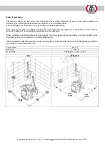
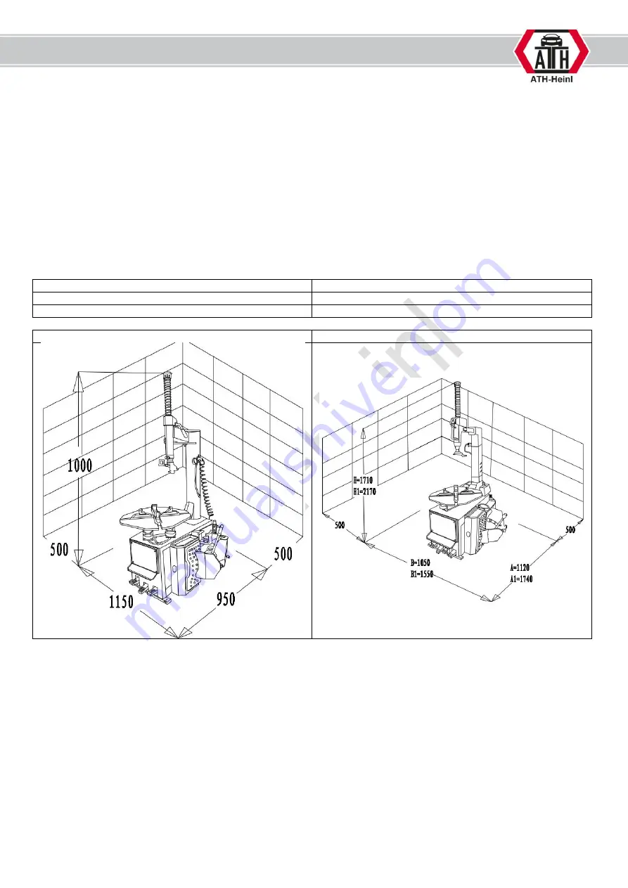
Place of installation 


The  machine  should  be  kept  away  from  flammable  and  explosive  materials  as  well  as  from  solar  radiation  and 

intensive light. The machine should also be installed in a well-ventilated place.  

The tire changer must be placed on a concrete floor or similar solid flooring. 


When selecting the place of installation, besides the soil condition also the guidelines and instructions of the accident 

prevention regulations and workplace regulations must be observed. 


When installing on an intermediate ceiling the capacity has to be checked before. Generally it is recommended to ask 

a technical expert when installing on an intermediate ceiling. 


It is not allowed to install the machine outside, but only inside, as the machine has no corresponding safety provisions 

(IP-protection, zinc coated and so on)  


Temperature 

4-40 °C 

Sea level  

< 1000 m 

Air humidity 

50% at 40°C – 90% at 20 °C 


M32 

M52 / M72 


Summary of Contents for ATH M32

Page 1: ...U US SE ER R S S M MA AN NU UA AL L A AT TH H M M3 32 2 A AT TH H M M5 52 2 A AT TH H M M7 72 2 ...

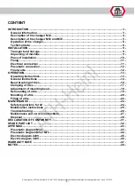
Page 2: ...onnection 11 Pneumatic connection 12 Final works 12 OPERATION 13 Operating instructions 13 General instructions 14 Bead breaking of tires 16 Clamping of tires 17 Adjustment of mounting head 18 Demounting of a tire 19 Mounting of a tire 20 Filling of a tire 22 MAINTENANCE 24 Safety regulations for oil 24 Maintenance instructions 25 Troubleshooting 26 Maintenance and service instructions 27 Disposal...

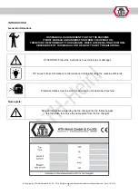
Page 3: ...Y FOR DAMAGES WHICH ARE RESULTING FROM NON OBSERVANCE OF THIS MANUAL OR THE GUILTY SAFETY REGULATIONS ATTENTION Follow the instructions to avoid injuries or damages TIP Gives further informations to the functions and tips for using the machine efficiently Protective clothes must be worn for all works on the described machine Name plate Note all informations regarding the tire changer into the foll...

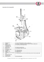
Page 4: ...3 Mounting head For mounting demounting of tires 4 Compressed air maintenance unit 5 Bead breaker For fixing the bead shovel 6 Bead shovel For breaking the bead off the rim 7 Foot pedal control 10 Turntable For rotating the tires 11 Clamping jaws For clamping the rim 12 Inflator For filling the tire 13 Adjustment screw for swivel arm For adjusting the arrestor for the horizontal movement of the mo...

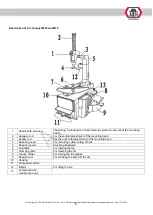
Page 5: ...on rod For the vertical adjustment of the mounting head 3 Square rod For the horizontal adjustment of the mounting head 4 Mounting head For mounting demounting of tires 5 Mounting tower Swiveling backward 6 Turntable For rotating the tire 7 Clamping jaws For clamping the rim 8 Grease holder For storing the tire grease 9 Bead shovel For breaking the bead off the rim 10 Housing 11 Foot pedal control...

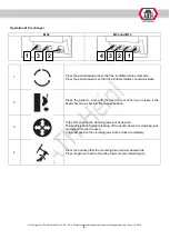
Page 6: ...ckwise 2 Press the pedal to work with the bead shovel When you release it the bead shovel goes back to the original position 3 In the first position the clamping jaws will be opened The middle position slight pressing of the pedal closes the clamping jaws and adjust it to the tire used In the last position the clamping jaws will be closed completely 4 Press the pedal so that the mounting tower swi...

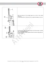
Page 7: ...ocking 2 the mounting head will be fixed in the vertical movement The adjusting screw on the swivel arm 13 adjusts the distance to the rim By pressing the button 1 both the hexagon 2 and the square 3 will be fixed in the adjusted position By pulling the button the fixing will be released and the mounting head 4 can be adjusted ...

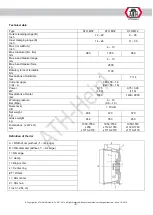
Page 8: ...f turntable Nm 1100 Revolutions of turntable rpm 7 7 14 Current supply V Hz A 380 50 16 220 50 16 Power kW 0 75 1 10 0 75 0 90 1 10 Revolutions of motor rpm 1380 1400 2800 Working pressure Bar Mpa 8 10 0 8 1 0 Noise level dB 70 dB Net weight kg 204 270 370 Gross weight kg 242 350 450 Dimensions L xW x H mm 1050 1550 x950 x1710 2170 1050 1550 x1120 1740 x1710 2170 1050 1550 x1120 1740 x1710 2170 De...

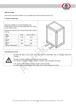
Page 9: ...achine should only be transported with the original packing Data M32 M52 und M72 Width mm 1150 1150 Length mm 900 850 Height mm 980 980 Storage temperature 25 to 55 C Unpacking of machine Remove the upper cover of the carton and make sure that there were no damages during the transport Remove the safety bolts to get the machine from the pallet For taking the machine from the pallet use a suitable ...

Page 10: ...g When selecting the place of installation besides the soil condition also the guidelines and instructions of the accident prevention regulations and workplace regulations must be observed When installing on an intermediate ceiling the capacity has to be checked before Generally it is recommended to ask a technical expert when installing on an intermediate ceiling It is not allowed to install the ...

Page 11: ...he general and local regulations must be observed Therefore this step must be performed only by an expert Pay attention to the correct current supply see technical data The connection should be made with a 5 phase 16 A CEE plug not in scope of delivery The machine must be grounded The voltage deviation should be max 0 9 1 1 times of the nominal voltage range and the frequence deviation should be m...

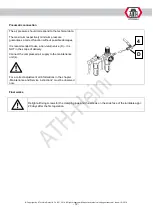
Page 12: ... correct function without possible damages It is recommended to use a non return valve D it is NOT in the scope of delivery Connect the compressed air supply to the maintenance unit 4 For a correct adjustment all informations in the chapter Maintenance and Service instructions must be observed now Final works Retight all fixing screws for the clamping jaws and the screws on the slide face of the t...

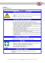
Page 13: ... has to be checked Faulty tires have to be made unusable While inflating the tire position a safety device for collecting parts which blow away Keep persons away from the danger zone On tire changers with vertical positioned tires the working with heavy weight tires e g earth mover tire molds must be made by 2 persons At tires with a diameter 1 4 m or a weight 200 kg safety devices against falling...

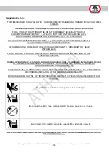
Page 14: ...MUST NOT HAVE ANY DAMAGES PAY ATTENTION TO POSSIBLE SPECIAL MOUNTING OR DEMOUNTING INSTRUCTIONS OF THE TIRE MANUFACTURER DURING OPERATION PAY ATTENTION TO DANGEROUS SITUATIONS IF THERE ARE ANY DANGERS SWITCH OFF THE MACHINE IMMEDIATELY DISCONNECT THE CURRENT SUPPLY AND THE AIR SUPPLY FOLLOWING CONTACT YOUR DISTRIBUTOR DURING MOUNTING OR DEMOUNTING OR INFLATING OF TIRES OBSERVE STRICTLY THE GUIDELI...

Page 15: ...e is no drop center In some countries the sale of this type of rims is not allowed At some rims the drop center in the middle of the rim is very deep so that the tires must be pressed into very deep while mounting or demounting This increases the danger that the tire will be damaged Some tires have a pressure control system While mounting or demounting a tire this system may not be damaged ...

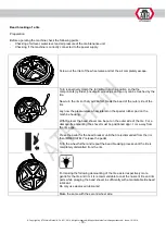
Page 16: ... of the outer side of the rim Lay now the pressureless wheel lateral on the special rubber pad on the machine housing With the lever the bead shovel can be put on the outer side of the tire For a damage free mounting the shovel must be positioned appr 1 cm away from the rim edge Press the pedal for the bead breaker until the tire is dismantled from the rim then IMMEDIATELY release the pedal Turn t...

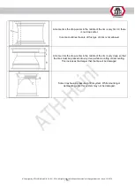
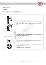
Page 17: ...ing head into the highest and very back position and arrest it again At the machines M52 M72 the mounting tower must be swiveled to the back Rims with an asymmetric drop center must be positioned in that way so that the narrow rim shoulder is at the top It is recommendable to clamp light alloy rims only from outside and to use plastic braces for not damaging them Press the pedal slightly for adjus...

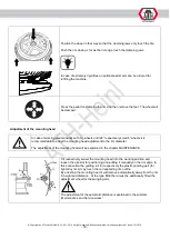
Page 18: ...all 8 wheels it is recommendable to adapt the mounting head adjustment to the rim diameter The adjustment of the mounting head will be explained in the chapter MAINTENANCE Tilt respectively swivel the mounting head into the working position and loosen the arrestor for positioning and putting it manually on the rim edge In this connection the guiding roll 3 respectively the plastic grinding part fo...

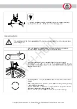
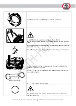
Page 19: ...ly 10 cm before the mounting head Push down the tire bead on the opposite side of the mounting head Afterwards lift the tire with a tire lever over the mounting head While lifting the tire will slide into the drop center of the rim and enables therefore an easy and damage free mounting Press the pedal for turning the turntable so that the clockwise rotation can be started Hold thereby the tire lev...

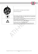
Page 20: ...ift the tire directly under the mounting head Lever now the tire bead over the rim and start the rotation in the same way as with the upper bead After demounting press the pedal for swivelling back of the mounting tower so that it turns back Now remove the wheel Mounting of a tire The guidelines of WdK Trade association of the German rubber industry has to be observed when mounting a tire The valv...

Page 21: ...ng head Put now the tire slant on the rim so that the mounting head do not touch tire parts while swiveling Swivel the mounting tower by pressing the corresponding pedal to the fore Position the tire so that the tire bead is under the nozzle but still on the guideway of the mounting head However please note that the tire opposite of the mounting head is in the drop center of the rim Now start the ...

Page 22: ...same way as described for the first bead Here must also be paid attention to the correct position of the tire opposite of the mounting head Now start the rotation of the turntable Pay attention to a correct bead run An inobservance can lead to heavy damages on the tire Finally loosen the rim clamping for removing the wheel Filling of a tire The max pressure of the tire may not be more then 3 5 bar...

Page 23: ...e it by removing the inner valve Afterwards the valve must be quickly inserted again Make sure that the tire was filled with the correct pressure pay attention here to the instructions of the manufacturer A too low tire pressure can lead to a higher wear and a shortened endurance of the tire The interior of the tire can also be damaged The tire pressure has to be checked once a week Check the tire...

Page 24: ... complete compressed air out of the machine press the pedal for the bead breaker several times Works on the electrical part of the machine respectively on the supply lines are only allowed to be done by technicians respectively electrically skilled persons Safety regulations for oil ALWAYS CONSIDER THE LEGAL REGULATIONS RESPECTIVELY THE HANDLING OF USED OIL DISPOSE USED OIL ONLY THROUGH A CERTIFIE...

Page 25: ...68 Viscosity ISO HG category Monthly Service on the compressed air maintenance unit see maintenance and service instructions Quarterly Lubrication grease pistol of pedals on the valve blocks and guiding pieces in the interior of the machine Removing the collected dirt in the interior of the machine Checking of pneumatic cylinder and stopper of the tilting function Checking of the holder of motor a...

Page 26: ...S NOT SWIVEL OR SWIVELS TOO SLOW Air pressure Check if the needed air pressure is connected to the machine Air lines Check if all air lines on the machine are connected correctly and that there is no leakage Regulating screws Adjust the regulating screws on the valve of the pedals respectively check those for damages Cylinder Check wear of sealing kits respectively cylinders TURNTABLE DOES NOT WOR...

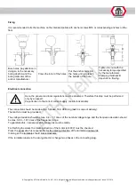
Page 27: ...l viscosity SAE20 Check the rate of injection of the oil in the viewing glass 4 The oiler is working correctly if one drop of oil injects automatically into the compressed air system while pressing the bead breaker twice If this is not the case the oil quantity to be injected has to be adjusted with the regulating screw C Normally the screw has to be tightened completely clockwise and then opened ...

Page 28: ...ylinder will be adjusted By tightening respectively loosening the nut A the automatic distance to the rim will be adjusted SWIVELLING SPEED By opening respectively closing the valves A B the swivelling speed forward or backward can be adjusted CLEANING OF VALVE BLOCK Disconnect the air lines H from the valve block V Clean the valve block V with compressed air possibly it must be changed Clean the ...

Page 29: ... 6 7 mm The roller 3 is laying on the rim flange After the adjustment make sure that both setscrews 2 and the locking screw 1 are fastened again CONTROLLING AND REFILLING OF GEAR OIL Turn the turntable into a position so that you can reach the oil filler easily Remove now the oil filler cap 3 Insert a flexible and transparent hose into the opening until it reach the bottom of the gear Keep now one...

Page 30: ...nd supply lines Remove all non metallic material and store it according to the local regulations Remove the oil of the machine and store it accoriding to the local regulations Dispose all metallic materials The machine contains some substances which pollute the environment and are dangerous for the human body if they are not handled correctly ...

Page 31: ...senberg Germany Prüfinstitut Institut of Quality Institut de qualité Instituto de calidad SGS Supervice Gözetme Etüd Kontrol Servisleri A S Baglar Max Osmanpasa Cad No 95 Is Istanbul Plaza A Girisi Günesli 34209 Istanbul TURKEY Referenznummer der technischen Daten Reference number for the technical data Numéro de référence des données techniques Número de referencia de los datos técnicos TCF MD 14...

Page 32: ... Copyright by ATH Heinl GmbH Co KG 2014 All rights reserved Misprint and technical changes reserved Issue 12 2014 32 SPARE PARTS LIST ...

Page 33: ... Copyright by ATH Heinl GmbH Co KG 2014 All rights reserved Misprint and technical changes reserved Issue 12 2014 33 Housing ...

Page 34: ... Copyright by ATH Heinl GmbH Co KG 2014 All rights reserved Misprint and technical changes reserved Issue 12 2014 34 Mounting tower M32 ...

Page 35: ... Copyright by ATH Heinl GmbH Co KG 2014 All rights reserved Misprint and technical changes reserved Issue 12 2014 35 Mounting tower M52 and M72 ...

Page 36: ... Copyright by ATH Heinl GmbH Co KG 2014 All rights reserved Misprint and technical changes reserved Issue 12 2014 36 Turntable M32 and M52 ...

Page 37: ... Copyright by ATH Heinl GmbH Co KG 2014 All rights reserved Misprint and technical changes reserved Issue 12 2014 37 Turntable M72 ...

Page 38: ... Copyright by ATH Heinl GmbH Co KG 2014 All rights reserved Misprint and technical changes reserved Issue 12 2014 38 Bead breaker ...

Page 39: ... Copyright by ATH Heinl GmbH Co KG 2014 All rights reserved Misprint and technical changes reserved Issue 12 2014 39 Motor ...

Page 40: ... Copyright by ATH Heinl GmbH Co KG 2014 All rights reserved Misprint and technical changes reserved Issue 12 2014 40 Pedal unit M32 ...

Page 41: ... Copyright by ATH Heinl GmbH Co KG 2014 All rights reserved Misprint and technical changes reserved Issue 12 2014 41 Pedal unit M52 and M72 ...

Page 42: ... Copyright by ATH Heinl GmbH Co KG 2014 All rights reserved Misprint and technical changes reserved Issue 12 2014 42 Maintenance unit and filling device ...

Page 43: ... Copyright by ATH Heinl GmbH Co KG 2014 All rights reserved Misprint and technical changes reserved Issue 12 2014 43 APPENDIX Pneumatic diagram M32 ...

Page 44: ... Copyright by ATH Heinl GmbH Co KG 2014 All rights reserved Misprint and technical changes reserved Issue 12 2014 44 Pneumatic diagram M52 M72 ...

Page 45: ... Copyright by ATH Heinl GmbH Co KG 2014 All rights reserved Misprint and technical changes reserved Issue 12 2014 45 Elektric diagram 220V ...

Page 46: ... Copyright by ATH Heinl GmbH Co KG 2014 All rights reserved Misprint and technical changes reserved Issue 12 2014 46 Elektric diagram 380V ...

Page 47: ...ung entstehen fallen nicht in die Gewährleistung Für Anlagen die nicht durch einen zugelassenen Monteur der Fa ATH montiert wurden beschränkt sich die Gewährleistung auf die Bereitstellung der erforderlichen Ersatzteile Damage caused by improper handling lack of maintenance or mechanical damage does not fall into the warranty For machines that are not installed by a licensed technician from the co...

Page 48: ...e stated instructions in this user s manual and or other enclosed instructions ordinary wear of single parts which require a service to maintain the product in a safe operating condition all components which were damaged during transport other components which are not explicitly listed but are handled as general wear parts water damages caused e g by rain excessive humidity corrosive environment o...

Page 49: ... Copyright by ATH Heinl GmbH Co KG 2014 All rights reserved Misprint and technical changes reserved Issue 12 2014 49 NOTES ...

Page 50: ... Copyright by ATH Heinl GmbH Co KG 2014 All rights reserved Misprint and technical changes reserved Issue 12 2014 50 ...

Page 51: ... Copyright by ATH Heinl GmbH Co KG 2014 All rights reserved Misprint and technical changes reserved Issue 12 2014 51 ...

Page 52: ... Copyright by ATH Heinl GmbH Co KG 2014 All rights reserved Misprint and technical changes reserved Issue 12 2014 52 ...

Reviews: