


® Copyright by ATH-Heinl GmbH & Co. KG, 2014, All rights reserved /Misprint and technical changes reserved / Issue: 12/2014
- 29 -
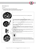
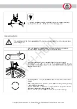
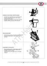
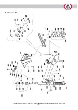
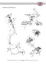
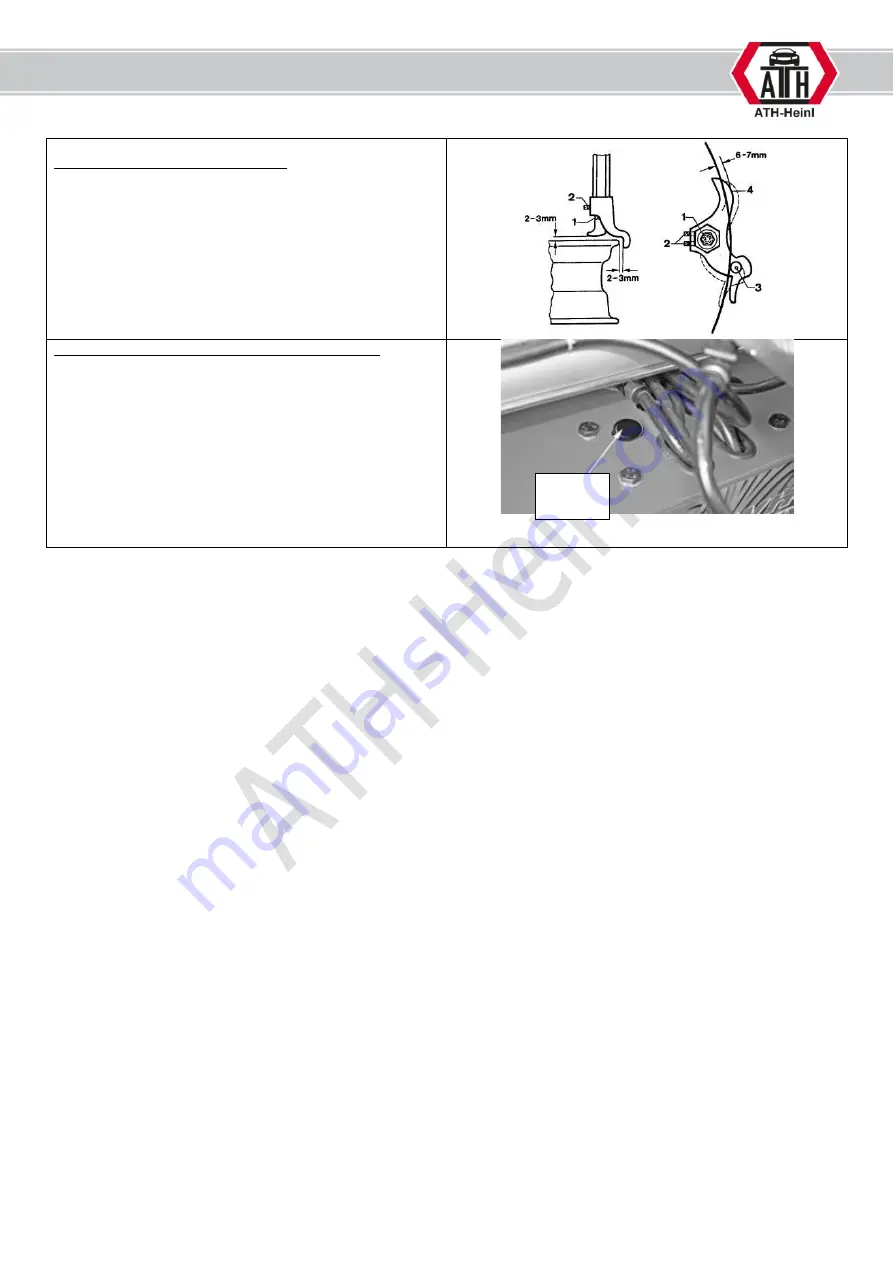
MOUNTING HEAD ADJUSTMENT
-
Loosen the locking screw (1) on the mounting head.
-
By tightening respectively loosening of both
setscrews (2) the angle of the mounting head to the
rim can be adjusted. The bead guide (4) overlap the
rim flange thereby appr. 6 – 7 mm. The roller (3) is
laying on the rim flange.
-
After the adjustment make sure that both setscrews
(2) and the locking screw (1) are fastened again.
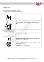
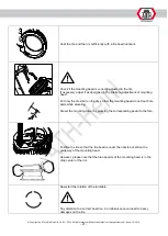
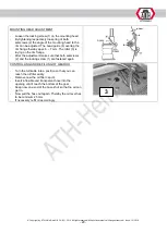
CONTROLLING AND REFILLING OF GEAR OIL
-
Turn the turntable into a position so that you can
reach the oil filler easily.
-
Remove now the oil filler cap (3).
-
Insert a flexible and transparent hose into the
opening until it reach the bottom of the gear .
-
Keep now one end of the hose shut so that no air can
get in.
-
Now pull the hose out again. Thereby the oil level has
to be minimum 25 mm.
-
If necessary refill oil accordingly.
3


