background image


® Copyright ATH-Heinl GmbH & Co. KG, 2017, All rights reserved. / Misprint and technical changes reserved / Issue: 07/2018 

- 7 - 

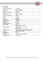
Technical data 


Maximum wheel weight 

< 160 kg 

Rim diameter 

Car: 4 

 20 inch 

Truck: 13 - 24 inch 

Rim width 

5 - 20 inch 

Maximum wheel diameter 

1200 mm 

Balancing accuracy 

Car: +/- 1,0 g 

Truck: +/- 10,0 g 

Accuracy of measurement 

>99% 

Cycle time 

Car: 13 s 

Truck: 25 s 

Motor 

0,60 kW 

Power supply 

3/400V/50 Hz 

Needed air supply 

6-8 bars 

Motor rpm 

1370 rpm 

Protection type 

IP 22 

Noise level in operation 

<70 dB(A) 

Shaft diameter 

40 mm 

Balancing programs 

Mode “Dynamic” (Standard)


Mode “Static”


Standard “ALU

-

1”, “ALU

-

2” 

-Mode 

Mode “ALU

-

S”


Additional functions 

HID (weight positioning behind spokes) 

 Mode 

Setting of measuring units in g / Oz, mm / inch 

Anchoring 

Bolt anchors: M8 x 100 

Quantity anchors 

2 pieces 

Dimension 

(L x W x H) 

approx. 1640 x 1090 x 1900 mm 

Net / Gross weight 

305 / 330 kg 


Summary of Contents for ATH W142

Page 1: ...USER S MANUAL ATH W142 ...

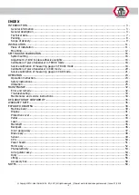
Page 2: ...ation of measuring gauge in TRUCK mode 18 Calibration of piezo transducer in CAR mode 20 Service calibration of measuring gauge in CAR mode 21 OPERATION 23 Operation instruction 23 Safety instructions 24 Utilization 25 MAINTENANCE 32 Error and remedy 32 Troubleshooting 33 Maintenance and service instructions 34 DECLARATION OF CONFORMITY 35 WARRANTY NOTE 36 EXPLODED DRAWING 38 Machine body 39 Displ...

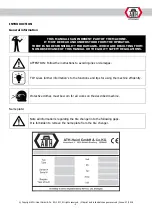
Page 3: ...OR DAMAGES WHICH ARE RESULTING FROM NON OBSERVANCE OF THIS MANUAL OR THE GUILTY SAFETY REGULATIONS ATTENTION Follow the instructions to avoid injuries or damages TIP Gives further information s to the functions and tips for using the machine efficiently Protective clothes must be worn for all works on the described machine Name plate Note all information s regarding the tire changer into the follo...

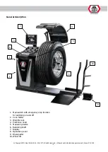
Page 4: ...changes reserved Issue 07 2018 4 General description 1 Main switch with emergency stop function for switching on and off 2 Cone holder 3 Weights rack 4 Protective hood 5 Measuring device 6 Balancing shaft 7 Display 8 Operation panel 9 Brake pedal 10 Wheel lift 7 2 1 8 3 5 9 6 4 10 ...

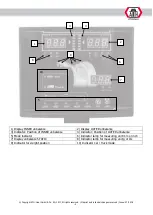
Page 5: ...unbalance 2 Display OUTER unbalance 3 Indicator Position of INNER unbalance 4 Indicator Position of OUTER unbalance 5 Mode indicator 6 Indicator lamp for measuring unit mm or inch 7 Display unbalance STATIC 8 Indicator lamp for measuring unit g or Oz 9 Indicator for weight position 10 Indicator car truck mode 1 3 4 2 5 6 7 8 9 10 ...

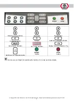
Page 6: ... 2018 6 Distance rim to machine Rim width Rim diameter Calibration button Self test Switchover DYNAMIC STATIC ALU program selection Car truck selection Display of exact unbalance 5g Switchover for input parameters button button Do only use your fingers for operating the machine In no case use sharp objects ...

Page 7: ...ycle time Car 13 s Truck 25 s Motor 0 60 kW Power supply 3 400V 50 Hz Needed air supply 6 8 bars Motor rpm 1370 rpm Protection type IP 22 Noise level in operation 70 dB A Shaft diameter 40 mm Balancing programs Mode Dynamic Standard Mode Static Standard ALU 1 ALU 2 Mode Mode ALU S Additional functions HID weight positioning behind spokes Mode Setting of measuring units in g Oz mm inch Anchoring Bo...

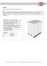
Page 8: ...mages If there is a damage or if goods are missing refuse delivery note it also on the documents and inform your distributor Instructions for transport and storage Lift with care using suitable means of support for the load in perfect working order Avoid sudden jolts and tugs watch out for uneven surfaces bumps etc After removing the packing check that they are taken to special waste collecting ar...

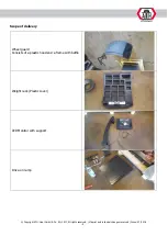
Page 9: ... KG 2017 All rights reserved Misprint and technical changes reserved Issue 07 2018 9 Scope of delivery Wheel guard Consists of a plastic hood and a frame with baffle Weight rack Plastic cover LED Monitor with support Drive on ramp ...

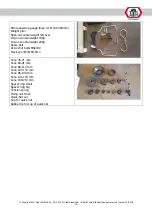
Page 10: ...k on counterweight remover Clip on counterweight 100g Clip on counterweight 200g Spare belt 2x Anchor bolts M8x100 Hex keys 3 5 6 8 10 13 Cone 45 71 mm Cone 69 91 mm Cone 89 114 mm Cone 107 133 mm Cone 96 149 mm Cone 141 170 mm Cone 169 214 mm Spacer ring small Spacer ring big Tension spring Fixing nut Truck Quick Nut car Cup for quick nut Rubber lip for cup of quick nut ...

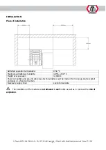
Page 11: ...ion temperature 0 50 C Maximum admitted air humidity 85 at 30 C Height over sea level 1000m Power connection and ground cable see technical data could be made in form of plug device socket and plug or a fixed connection Necessary supply lines see technical data The installation of the machine is not allowed in wet rooms as well as in rooms with a risk of explosion ...

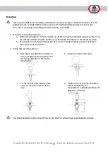
Page 12: ...t points In no case lift the machine at other points as e g the shaft the display or the accessory plate b The machine must stand firmly on the floor at the intended support points if necessary there must be used washers 2 Fixing with security anchors a Bore holes pay attention in doing so to the necessary boring depth A and the boring diameter of the anchor manufacturer b Clean the inner of the h...

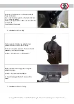
Page 13: ... pole flat cable for keyboard and prepare the not connected end for next step Remove the fixing screws oft he body Place the weight tray on the machine body Connect the cable to the keyboard and fix the cable by using zip tie Take the screws and fix the plastic cover on the machine body 4 Mounting of protective hood Unpack the wheel guard and place near by the machine ...

Page 14: ...he baffle and connect to the above shaft Now fix it with the screw 5 Installation of the display Fix the support of display by using the four attached screws on the machine body Remove the top two screws of the cover to add the cables into the cable canal Connect now the cables on the machine Fix the monitor on the support by using the attached screws Connect the cables with the display At the end...

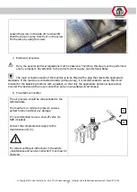
Page 15: ...a plug that meets the appropriate standards If the machine is connected directly without plug it is recommended to secure the circuit breaker for the balancing machine with a padlock so that only the appropriate personnel have access Connect the machine with an own connection and an own suitable circuit breaker 8 Pneumatic connection The air pressure should be corresponded to the technical data Th...

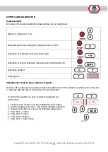
Page 16: ...nally 3D Calibration program HID program Adjustment of kind to place adhesive weights By help of this setting can be selected whether the attachment of the adhesive weights by measuring arm or manually with the help of a laser line at 6 o clock position To get into the system you have to press the adjacent key combination 1 First press the C button and then additionally the T button 2 Now the disp...

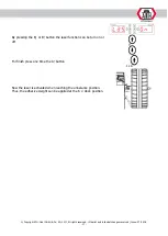
Page 17: ...al changes reserved Issue 07 2018 17 By pressing the B or B button the laser function can be turn on or off For finish press one time the A button 1x Now the laser is activated when reaching the unbalance position Thus the adhesive weight can be applied at the 6 o clock position ...

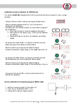
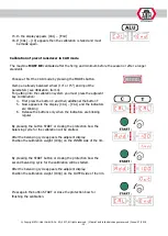
Page 18: ...inking 3 Release the buttons only when the indicators are blinking regular By pressing the button START or closing the protection bow the balancing cycle for the calibration will be started After the balancing cycle appears the adjacent display Position the calibration weight 200g on the INNER side of the rim By pressing the START button or closing the protection bow the second balancing cycle for...

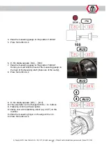
Page 19: ...e measuring gauge on the position 300mm Hereby you must take the head of the measuring gauge on the bowl of the balancing shaft Take care of the cavity 8 Press the button ALU 9 In the display appears CAL 22 5 10 This parameter can be changed with D D buttons 11 Following confirm with ALU button 12 Clamp now a corresponding wheel e g 22 5 on the machine 13 Place the measuring finger on the edge of ...

Page 20: ...acent key combination 4 First press the button C and then additional the button T 5 Now appears in the display CAL CAL and the indicators are blinking 6 Release the buttons only when the indicators are blinking regular By pressing the button START or closing the protection bow the balancing cycle for the calibration will be started After the balancing cycle appears the adjacent display Position th...

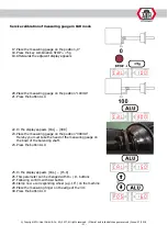
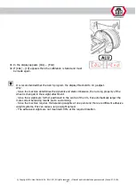
Page 21: ...uring gauge on the position 100mm 21 Press the button ALU 22 In the display appears CAL 300 23 Place the measuring gauge on the position 300mm Hereby you must take the head of the measuring gauge on the bowl of the balancing shaft 24 Press the button ALU 25 In the display appears CAL 15 0 26 This parameter can be changed with D D buttons 27 Following confirm with ALU button 28 Clamp now a correspo...

Page 22: ...just Why Since the machine determines the dynamic and static imbalance the running property of the wheel is changed in the weight attachment Since the weights are further positioned in the centre of the rim this automatically larger the more correct balancing results are to succumbing Since the machine requires the balancing weights at one point and there are different adhesive weight systems this...

Page 23: ...ir Wear close fitting working clothes possibly with Velcro fastener on arms and legs Protective cap for long hairs If possible use transport devices and lifting devices and transport in pairs Pay attention to an ergonomic workplace design Right lifting and carrying for the backbone BEHAVIOUR IN CASE OF ERROR In case of security relevant errors stop immediately the operation and secure it against u...

Page 24: ...product to be treated In general the operator shall eliminate possible residual risks before by a proper and careful attitude Always use correct and proper working materials Wear suitable protective clothing respectively protective agents e g protective glasses ear protection safety shoes and so on Consider given information instructions and technical data of the machine producer respectively of t...

Page 25: ... there are 2 simple possibilities to clamp the wheel a The first possibility for cantering is as shown adjacent Here the rim will be clamped with a cone from outside on the balancing shaft When using the biggest cone must be used additionally the adaptor for the clamping hood This possibility increases the danger of clamping errors and is only recommendable for steel rims b At the second possibili...

Page 26: ... determines the radial and lateral runout of a light alloy rim The balancing weights will be placed on predefined points ALU 2 This function determines the radial and lateral runout of a light alloy rim The balancing weights will be placed on predefined points ALUS This function determines the radial and lateral runout of a light alloy rim The balancing weights will be placed on points predefined ...

Page 27: ...ht ATH Heinl GmbH Co KG 2017 All rights reserved Misprint and technical changes reserved Issue 07 2018 27 4 Input of wheel parameters a Basically In the motorcycle mode must be used an optional test prod 100 mm ...

Page 28: ...atically the data of A and D Now the rim width must be entered with the buttons B B In the mode ALU2 and ALUS the following data must be entered A Distance from machine to first weight position B Distance from machine to second weight position D Rim diameter dE Rim diameter on the point for the weight In the measuring process first the measuring gauge should be moved to the first point after a sho...

Page 29: ...12 o clock Laser Position 12 o clock STA Position 12 o clock Laser ALU1 Position 12 o clock Laser Position 12 o clock ALU2 Position 12 o clock Laser Weight taking on the measuring arm ALUS Weight taking on the measuring arm Weight taking on the measuring arm a HID Function With the HID function it is possible to hide the external balancing weight behind the spokes This function is available in the...

Page 30: ...position with ALU After this appears in the display SPO 2 Turn now the wheel until the right spoke are at the position 12 o clock Confirm now this position with ALU After this the INNER UNBALANCE will be shown in the display and below of it SPL By turning the wheel until all diodes for the OUTER position illuminate the corresponding value will also be displayed Now place the weight on the measurin...

Page 31: ... changes reserved Issue 07 2018 31 Turn the wheel further until all diodes illuminate again for the outer position for localizing the second value in doing so the corresponding value will be displayed Now place the weight on the measuring gauge and put it by means of it on the rim ...

Page 32: ...easures against switching on Works on the electrical parts respectively the supply lines are only allowed to be done by skilled personal technicians Error and remedy The wheel balancer can display the following errors Error Reason Err 1 Err 2 1 No tire on the balancer to light tire on the balancer 2 Balancing shaft isn t fix 3 Wheel is not fixed well on the shaft 4 Weak tension on the belt Err 3 T...

Page 33: ...rake resistor respectively connection Motor makes noise Brake resistor defect respectively not connected Check brake resistor respectively connection Main board defect Contact the ATH Service Capacitor defect or not connected Check capacitor respectively connection Circuit breaker blows Main switch of machine is not correctly connected or there is a contact fault Check the electrical connections M...

Page 34: ...he motor with the clamping screw thus pay attention to the correct belt tension 4 Tighten the fixing screws of the motor again 5 Make a test run thus pay attention to that the belt does not drop down lateral 6 Mount the cover again Changing fuses 1 Take off carefully the cover weights rack 2 Take out the fuse from the power supply board 3 Exchange the new fuse with the old one thus only use fuses ...

Page 35: ...ach Rosenberg GERMANY Institute of Quality SGS Supervice Gözetme Etüd Kontrol Servisleri A S Baglar Max Osmanpasa Cad No 95 Is Istanbul Plaza A Girisi Günesli 34209 Istanbul TURKEY Reference number for the technical data TCF MD 140526 048 Number of the certificate 0263 IN IST 14 502756 AOO AKC OUCE 141003 Herewith we confirm that the above named machines are according to the named EC directives AT...

Page 36: ... of required spare parts Spare part Article number Quantity IMPORTANT NOTES Damage caused by improper handling lack of maintenance or mechanical damage does not fall into the warranty For machines that are not installed by a licensed technician from the company ATH the warranty is limited to the provision of necessary spare parts Damages in transit Obvious defect note on carrier s delivery note a ...

Page 37: ... the stated instructions in this user s manual and or other accompanying instructions normal wear of single parts which require a service to maintain the product in a safe operation condition each component which was damaged during transport other components which are not explicitly listed but are handled as general wear parts water damages caused e g by rain excessive humidity corrosive environme...

Page 38: ... Copyright ATH Heinl GmbH Co KG 2017 All rights reserved Misprint and technical changes reserved Issue 07 2018 38 EXPLODED DRAWING ATH W142 ...

Page 39: ... Copyright ATH Heinl GmbH Co KG 2017 All rights reserved Misprint and technical changes reserved Issue 07 2018 39 Machine body ...

Page 40: ...at washer Ø6 4 9 030301105 Nut M6 4 10 020601008 Handle 4 11 030101553 Bolt M10x30 4 12 030502006 Spring washer Ø10 4 13 030301107 Nut M10 1 14 030501006 Flat washer Ø10 4 15 020602075 ATH Front cover 1 16 05020030054 Decorative hook 4 17 030502002 Spring washer Ø4 4 18 030201003 Screw M4x10 4 19 05020030819 Baffle 1 20 030201783 Screw M4x8 2 21 05020030818 Baffle 1 22 021101013 Keyboard 1 23 0211...

Page 41: ...crew M8x20 4 8 030301103 Nut M4 2 9 020601257 Rear cover 1 10 05020110208 Connection plate 1 11 030201337 Screw M4x16 4 12 030201082 Screw M10x20 2 13 030301055 Nut M10 2 14 05020110200 Support bracket 1 15 030201004 Screw M4x12 6 16 05020110209 Cover plate 1 17 030201006 Screw M4x20 2 18 030201082 Screw M10x20 2 19 030301055 Nut M10 2 20 030301056 Nut M12 2 21 05020110264 Rotation seat 1 22 03050...

Page 42: ...30301002 Nut M8 1 5 030201061 Screw M8x12 1 6 030501005 Flat washer 8 1 7 020101080 Crash pad 1 8 05020050123 Pull rod 1 9 05020050113 Support rod 1 10 05020050122 Screw 1 11 030301056 Nut M12 1 12 030501007 Flat washer 12 1 13 05020050117 Bracket 1 14 030201043 Screw M6x16 3 15 020602099 Small cover 2 16 020602100 Big cover 1 17 030201041 Screw M6x10 2 18 05020050125 Flat washer 1 19 030301003 Nu...

Page 43: ...0201782 Screw M5x12 2 6 030201022 Screw M5x10 4 7 030301001 Nut M5 4 8 030201024 Screw M5x16 4 9 030301011 Nut M6 2 10 030101452 Bolt M6x16 2 11 05020170036 Axle 1 12 05020170035 Sleeve 2 1 13 020601296 Pedal 1 14 030201022 Screw M5x10 1 15 030501003 Flat washer 5 1 16 020703011 Torsional spring 1 17 05020170030 Swing rod 1 18 030201046 Screw M6x30 1 19 05020170032 Pdeal box 1 20 05020170033 Pdeal...

Page 44: ...rved Issue 07 2018 44 Laser ATH Reference Description Note x 1 021006039 Laser light source 5V Ø12x35 1 2 030201006 Screw M4x20 2 3 030202011 Screw M4x4 1 4 020601300 Laser light bracket 1 5 030201783 Screw M4x8 2 6 05020030826 Mounting plate 1 7 030501002 Flat washer Ø4 2 8 030301012 Nut M4 2 ...

Page 45: ...crew M6x20 3 3 030502004 Spring washer Ø6 3 4 030201004 Screw M4x12 4 5 030501004 Flat washer Ø6 3 6 05020070009 Photocell 1 7 0530207098 Bearing end cover 1 8 030802053 Bearing 6007 NSK 1 9 030303106 Round nut M35x1 5 1 10 030802002 Bearing 6006 NSK 1 11 030604023 Circlip 30 1 12 05020070304 Axis sleeve 1 13 05020070301 Adaptor 1 14 030201191 Screw M16x30 1 15 030502002 Spring washer Ø4 4 ...

Page 46: ...x7x18 1 3 030201453 Screw M5x10 2 4 05020050109 Switch plate 1 5 05020050108 Sleeve 1 6 030202023 Screw M8x8 1 7 030301002 Nut M8 2 8 030501125 Washer 8 1 9 030201068 Screw M8x45 2 10 030101365 Bolt with full thread M8x30 1 11 05020050101 Backpack seat 1 12 030201333 Screw M4x8 3 13 021006031 Microswitch YBLXW 5 11G1 1 14 020702031 Spring 1 15 05020050110 Backpack cover 1 16 030201340 Screw M4x30 ...

Page 47: ...uler 2 3 05020040034 Guide rod 1 4 05020040008 Pad 1 5 060204016 Slide block 1 6 030204001 Screw ST2 9x6 5 6 7 0500204140 Rod 1 8 020701066 Spring 1 9 05020140001 Nut sleeve 1 10 020601299 Rack 1 11 05020040091 Pull rod support 1 12 030201043 Screw 1 13 030502004 Soring washer 2 14 05020140002 Nut 2 15 030501004 Flat washer 6 2 16 030201063 Screw M8x20 2 17 030604101 Circlip 20 1 18 05020040090 In...

Page 48: ...Flat washer 10 1 4 030201083 Screw M10x25 1 5 05020020313 Brake block 1 6 030201042 Screw M6x12 1 7 030501005 Flat washer 8 1 8 030301002 Nut M8 1 9 030301002 Nut M8 1 10 05020020305 Axis 1 11 020203331 Cylinder 25x25 1 12 020203075 Elbow Ø4 G1 8 1 13 05020020306 Block 1 14 030903006 Cotter 2x20 2 15 020702027 Tension spring 1 16 020101080 Crash pad 1 17 05020020308 Limit stop 1 18 030301002 Nut M...

Page 49: ...7 2018 49 Sensor ATH Reference Description Note x 1 030301108 Nut M12 5 2 05020070029 Sensor flat gasket 2 3 021006034 Sensor horizontal Ø12 1 4 05020070097 Horizon bar 1 5 05020070096 Threaded rod 1 6 021006035 Sensor vertical Ø12 1 7 020402015 Sensor wire 3x0 75mm x1 5m 1 8 030502007 Spring washer 12 2 ...

Page 50: ...bH Co KG 2017 All rights reserved Misprint and technical changes reserved Issue 07 2018 50 CPU ATH Reference Description Note x 1 030201614 Screw M3x25 4 2 030502001 Spring washer 3 8 3 030301101 Nut M3 12 4 05020200005 CPU 1 ...

Page 51: ...rence Description Note x 1 030101303 Bolt M5x20 4 2 030502005 Spring washer 5 4 3 030501004 Flat washer 6 4 4 020404005 Transformer 380V 9V 1 5 030101022 Bolt M6x16 4 6 030301106 Nut M8 4 7 05020210005 Power board 380V 1 8 05020060030 Power board scalboard 1 9 030201614 Screw M3x25 5 10 05020060057 Cooling fin 1 11 030301101 Nut M3 15 ...

Page 52: ... 2018 52 Motor assy ATH Reference Description Note x 1 030101553 Bolt M10x30 4 2 030502006 Spring washer Ø10 4 3 030501006 Flat washer Ø10 4 4 030101094 Bolt M10x75 1 5 030301003 Nut M10 1 6 05020030829 Adjusting plate 1 7 020405010 Poly V belt 6PJ965 1 8 05020070306 Small belt pulley 1 9 020401103 Motor 1 ...

Page 53: ...8 53 Photoelectricity ATH Reference Description Note x 1 030201002 Screw M4x8 2 2 030502002 Spring pad 4 2 3 030501002 Flat gasket 4 2 4 021003002 Photoelectricity 32T 1 5 030301101 Nut M3 2 6 030502001 Spring pad 3 2 7 030501001 Flat gasket 3 2 8 0530207103 photoelectricity holder 1 9 030201265 Screw M3x10 2 ...

Page 54: ...ssue 07 2018 54 Air regulator assy ATH Reference Description Note x 1 030201002 Screw M4x8 2 2 0530108001 Holder 2 3 020203328 Quick connector 1 4 Ø10 EU 1 4 020201012 Barometer 1 5 020201005 Air filtration 1 6 020201004 Oil cup 1 7 020203035 Lock straight fittings Ø8 G1 4 1 8 030201002 Screw M4x8 4 ...

Page 55: ...uard M10 2 7 030201089 Screw M10x55 2 8 030201111 Screw M12x25 2 9 030301108 Nut M12 2 10 030301014 Nut M6 2 11 030501004 Flat wahser Ø6 2 12 030201045 Screw M6x25 4 13 05020130173 Handle 2 14 020602098 Cover 32 2 15 05020130156 Handle welding 1 16 030501006 Flat wahser Ø10 2 17 030202024 Screw M8x10 2 18 030802007 Deep groove ball bearing 6301 4 19 030501006 Flat wahser 10 4 20 030303003 Nut M10 ...

Page 56: ... Copyright ATH Heinl GmbH Co KG 2017 All rights reserved Misprint and technical changes reserved Issue 07 2018 56 Lifting ...

Page 57: ... Circlip for shaft Ø16 6 12 05020130017 Connecting plate 1 13 030502004 Spring wahser Ø6 4 14 030201062 Screw M8x16 4 15 05020130004 Fixing sleeve 2 16 030604018 Circlip for shaft Ø25 2 17 05020130005 Spacer bush 1 18 05020130003 Axis 1 19 05020130151 Baseplate 1 20 05020130014 Connector 2 21 05020130015 Axis 2 22 030604003 Circlip for shaft Ø10 2 23 060221002 Cylinder Ø75 2 24 05020130019 Adjusta...

Page 58: ... Copyright ATH Heinl GmbH Co KG 2017 All rights reserved Misprint and technical changes reserved Issue 07 2018 58 Accessory box ...

Page 59: ...0530201039 Cone 4 1 11 020403005 Poly V belt 6PJ965 1 12 022102004 Wrench 3mm 1 13 022102009 Wrench 5mm 1 14 022102002 Wrench 6mm 1 15 022102028 Wrench 8mm 1 16 022102022 Wrench 10mm 1 17 022102023 Wrench 16mm 1 18 022102005 Hammer 1 19 022102006 Weight 100g 1 20 022102015 Weight 200g 1 21 20601279 Quick nut 40mm handball 1 22 020101001 Rubber gasket 1 23 20601001 Bowl 1 24 020601002 Small reverse...

Page 60: ... Copyright ATH Heinl GmbH Co KG 2017 All rights reserved Misprint and technical changes reserved Issue 07 2018 60 NOTES ...

Page 61: ... Copyright ATH Heinl GmbH Co KG 2017 All rights reserved Misprint and technical changes reserved Issue 07 2018 61 ...

Page 62: ... Copyright ATH Heinl GmbH Co KG 2017 All rights reserved Misprint and technical changes reserved Issue 07 2018 62 ...

Page 63: ... Copyright ATH Heinl GmbH Co KG 2017 All rights reserved Misprint and technical changes reserved Issue 07 2018 63 ...

Page 64: ... Copyright ATH Heinl GmbH Co KG 2017 All rights reserved Misprint and technical changes reserved Issue 07 2018 64 ...

Reviews: