background image


© Copyright ATH-Heinl GmbH & Co. KG, 2017, All rights reserved. / Printing errors and technical changing´s reserved / Version: 02/2017 

- 44 - 


Main board broken 

Contact ATH-Service team 


1

More causes of "bad" results: 

Use of different adapters and resulting clamping errors. 

When using adapters, please pay attention to the installation instructions. 

Clamping by means of cones via a worn centre hole of the rim, differences of up to 10g may be 

possible. 

Unbalance of the tire on the vehicle can cause an imbalance on the brake drum or disc or worn 

mounting holes in the rim or brake. In such a case, readjustment is advisable without first removing 

the wheel. 


Maintenance and service instructions 


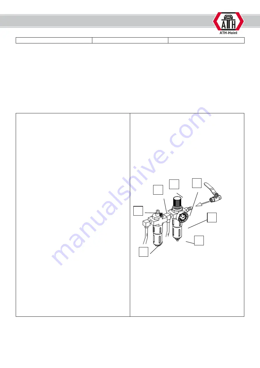
AIR MAINTENANCE UNIT 
 

PRESSURE REGULATION: 

-


Check the working pressure, which is indicated 

in the manometer (1). This must correspond to 

the technical data. 

-


The working pressure can be set by means of 

pressure regulator (A). 

-


Pull up the pressure regulator to make 

adjustments. 

-


To increase the pressure in the machine, turn 

the knob clockwise, to reduce it, turn it counter 

clockwise. 


OIL TANK 

-


Check the oil level in the oil tank (3) 

-


Remove the oil tank 

-


Now fill the container with a pneumatic oil with 

the viscosity SAE20 


-


Check the injection quantity of the oil through 

the inspection glass (4). The oiler functions 

correctly when a drop of oil is automatically 

injected into the compressed air system when 

the trigger is pressed twice. 

-


If this is not the case, the oil quantity to be 

injected must be adjusted via the regulating 

screw (C). 

As a rule, the screw must be closed completely 

clockwise and then reopened approximately ¼ 
to ½ turn by turning counter clockwise. 


WATER SEPERATOR 

-


Check the water level in the separator (2). 

-


The water is drained by opening the valve (B). 


Adjustment of drive belt tension 

1.


Carefully remove the cover (weight tray). 

Summary of Contents for ATH W82

Page 1: ...andleiding AT 150033 Bandenbalanceerapparaat ATH W82 MSH equipment Appelmarkt 7 1681 PE Zwaagdijk Oost Tel 0228 561100 Fax 0228 561112 Mail info msh equipment nl Website www msh equipment nl Taal engels ...

Page 2: ...USER S MANUAL ATH W82 ...

Page 3: ...libration of the wheel width measuring device 28 OPERATION 29 Operation instruction 29 Safety instructions 30 Utilization 31 MAINTENANCE 42 Error and remedy 42 Troubleshooting 43 Maintenance and service instructions 44 DECLARATION OF CONFORMITY 46 WARRANTY NOTE 47 SPARE PART BOOK 49 Machine 50 Display 52 Assistant body 54 CPU 55 Display board 56 Power board 57 Pneumatic control board 58 Air mainte...

Page 4: ...LITY FOR DAMAGES WHICH ARE RESULTING FROM NON OBSERVANCE OF THIS MANUAL OR THE GUILTY SAFETY REGULATIONS ATTENTION Follow the instructions to avoid injuries or damages TIP Gives further information s to the functions and tips for using the machine efficiently Protective clothes must be worn for all works on the described machine Name plate Note all information s regarding the tire changer into the...

Page 5: ...ersion 02 2017 4 General specifications 1 Main switch with emergency stop function for switching on and off 2 Cone holder 3 Weights rack 4 Protective bow 5 Measuring device 6 Balancing shaft 7 Display 8 Operation panel 9 Pedal for fixing loosing of the wheel 10 Rim width measuring device 7 2 1 8 3 5 9 6 4 10 ...

Page 6: ...balancing programs 2 Distance from balancer to first position of counter weight 3 Diameter of wheel 4 Width of the wheel 5 Main menu F1 Start F2 Optimization program F3 Diagnosis F4 Settings F5 Calibration program 5 Value of unbalance INSIDE 6 Value of unbalance OUTSIDE 7 Location of counter weight INSIDE 8 Location of counter weight OUTSIDE 5 7 8 2 1 3 4 6 7 5 ...

Page 7: ...technical changing s reserved Version 02 2017 6 10 Buttons for direction up down right left OK button 11 Function buttons 12 ESC button to cancel 13 STOP button to exit 14 START button to start Operate the keys exclusively with your fingers Never use sharp objects 11 10 12 13 14 ...

Page 8: ...g time 7 12 s Motor 0 25 kW Electrical system 1 220V 50 Hz Power consumption 15W in Standby Balancing speed 180 rpm Protection class IP 54 Noise level 70 dB A Shaft diameter 40 mm Balancing programs Dynamic mode default Static mode Standard ALU 1 ALU 2 mode ALU S mode Additional functions OPT Optimization mode HID Behind spokes location mode Unit set up in g Oz mm inch Anchoring Anchor bolts M8 x ...

Page 9: ...t and amount of missing parts on the delivery note and report to the supplier Instructions for transport and storage Carefully raise the load properly with suitable in faultless condition tools Avoid jerks Beware of bumps crossbows etc Keep the removed packing parts in an area which is inaccessible to children and animals until disposal Storage temperature 10 C 60 C Humidity 20 95 Dimension Length...

Page 10: ...nd technical changing s reserved Version 02 2017 9 Additionally you will find an accessory package INSIDE the wheel balancer To get it you must tilt the machine slightly If something is missing in the scope of the delivery see packing list please contact our sales department ...

Page 11: ...ll rights reserved Printing errors and technical changing s reserved Version 02 2017 10 Scope of delivery Two pair of keys for side cover Wheel guard Consisting of two plastic parts and one frame with handle 19 inch LCD Monitor with bracket ...

Page 12: ...mensions 455 x 430 x 50 mm Mechanism for wheel cover Screw for fixing of wheel cover Fixing materials Packing dimensions 350 x 230 x 160 mm Accessory box Packing dimensions 385 x 240 x 280 mm Adhesive weight remover Counter weight 5g Counter weight 10g Counter weight 35g Counter weight 50g Counter weight 100g Counter weight plier Hex keys Cup for quick nut Rubber lip for cup Anchor bolts Shaft inc...

Page 13: ... GmbH Co KG 2017 All rights reserved Printing errors and technical changing s reserved Version 02 2017 12 Screws for shaft Fixing sleeve Cone 45 75 mm Cone 70 90 mm Cone 88 110 mm Cone 105 130 mm Spacer for Cone 105 130 mm ...

Page 14: ...TALLATION Place of installation Operating temperature 0 50 C Humidity 85 by 30 C Sea level 1000m Power connection grounding cable see technical data is too made with plug or direct connection Necessary cable See technical data The installation of the machine is not allowed in wet rooms as well as in rooms with a risk of explosion ...

Page 15: ...support points In no case lift the machine at other points as e g the shaft the display or the accessory plate b The machine must stand firmly on the floor at the intended support points if necessary there must be used washers 2 Fixing with security anchors a Bore holes pay attention in doing so to the necessary boring depth A and the boring diameter of the anchor manufacturer b Clean the inner of...

Page 16: ...ng shaft Clean the support before installation of the shaft Place broth marks on a line By help of the finger the user can pressure the inner shaft to the machine and begin with the rotation for fixing the shaft As soon as the shaft is completely screwed in both marks are not in line anymore Turn the shaft backwards until the marks are in line again ...

Page 17: ...oon as the position is correctly the shaft can be fixed by help of the screws 4 Installing of wheel cover Remove the upper cover of the box Fixing the mechanism on the balancer chassis by help of the screws spring rings and washers Connect the mechanism on the specified connection port Add cover of the box again on top and fix it ...

Page 18: ...cal changing s reserved Version 02 2017 17 Remove the handle of the frame for the wheel cover Remove the fixing screw on the shaft of the mechanism At first place the backside of wheel cover on the shaft Than take the frame and slide it through the backside wheel cover onto the shaft ...

Page 19: ...frame Connect both parts together and fix them by using two screws on the side Locate again the fixing screw on the shaft of the mechanism Install the handle on the frame 5 Install the monitor Attach the monitor support on the balancer by using the four screws Remove the upper two screws of the cable channel to place the connection cables of the monitor inside of this channel ...

Page 20: ...ging s reserved Version 02 2017 19 Now connect the cables to the balancer Install the monitor on the holder by using the four screws Connect the cables to the monitor Add again the two top screws on the channel 6 Install of tire width gauge Install the support on the frame of the wheel cover ...

Page 21: ...rved Printing errors and technical changing s reserved Version 02 2017 20 Install the arm on the frame of the wheel guard by using two hex bolts with washer spring ring and nut Fix the connection cable by using tie strips on the frame of the wheel cover ...

Page 22: ... using the arrow keys 8 Electrical connection Please observe the general as well as the local regulations Therefore this step may only be carried out by a trained specialist Pay attention to the necessary supply cable as well as the specified voltage see technical data The main connection cable of the machine must be provided with a plug which corresponds to the relevant standards If the machine i...

Page 23: ...ressure should correspond to the technical data The maximum or minimum pressure guarantees a perfect function without any damage It is recommended to use a shut off valve D NOT included Connect the compressed air supply to the maintenance unit 4 For correct setting all instructions in the article Maintenance and Service Instructions must now be observed D 4 ...

Page 24: ... All rights reserved Printing errors and technical changing s reserved Version 02 2017 23 SETTING AND CALIBRATION System setting Basic settings can be set with the system settings To access the setup menu press F4 button in the main menu ...

Page 25: ...inting errors and technical changing s reserved Version 02 2017 24 Calibration menu The balancer HAVE TO calibrate after installing the balancer before each main season or longer rest without use To enter the calibration system press the F5 button in main menu ...

Page 26: ... GmbH Co KG 2017 All rights reserved Printing errors and technical changing s reserved Version 02 2017 25 Calibration of piezo transducer Press the F1 button in calibration system and follow the instructions on the screen ...

Page 27: ...H Co KG 2017 All rights reserved Printing errors and technical changing s reserved Version 02 2017 26 Calibration of the measuring device Press the F2 button in the calibration system and follow the instructions on the screen ...

Page 28: ... Copyright ATH Heinl GmbH Co KG 2017 All rights reserved Printing errors and technical changing s reserved Version 02 2017 27 ...

Page 29: ...G 2017 All rights reserved Printing errors and technical changing s reserved Version 02 2017 28 Calibration of the wheel width measuring device Press the F3 button in the calibration system and follow the instructions on the screen ...

Page 30: ...ssed air Wear close fitting working clothes possibly with Velcro fastener on arms and legs Protective cap for long hairs If possible use transport devices and lifting devices and transport in pairs Pay attention to an ergonomic workplace design Right lifting and carrying for the backbone BEHAVIOUR IN CASE OF ERROR In case of security relevant errors stop immediately the operation and secure it aga...

Page 31: ...f the product to be treated In general the operator shall eliminate possible residual risks before by a proper and careful attitude Always use correct and proper working materials Wear suitable protective clothing respectively protective agents e g protective glasses ear protection safety shoes and so on Consider given information instructions and technical data of the machine producer respectivel...

Page 32: ...s shown below there are 2 easy ways to fix the wheel a The first way to mount a wheel is shown in the picture The rim is fixed by using a cone from the outside of the rim When using the largest cone the spacer ring must be used additionally This possibility increases the risk of clamping errors and is therefore only recommended for steel rims b By the second possibility at first you place the spri...

Page 33: ... attached to a middle position of the rim ALU 1 This function determines the height and side balance of an alloy rim The counter weights are attached to defined position on the wheel ALU 2 This function determines the height and side balance of an alloy rim The counter weights are attached to defined position on the wheel ALU 3 This function determines the height and side balance of an alloy rim T...

Page 34: ... Printing errors and technical changing s reserved Version 02 2017 33 For ALU 1 the following dimensions must be observed when applying adhesive weights 4 Input of tire dimension a Basics In motorcycle mode an optional measuring finger 100mm have to be used ...

Page 35: ...meter The input will be done automatically by locate the measuring device on the edge of the rim Hereby the Values A and D will be input automatically Now the tire width B can be measured by the second measuring device In Modes ALU2 and ALUS following dimensions have to be recoded A Distance between balancer and first point for adhesive weight B Distance between balancer and second point for adhes...

Page 36: ...easuring process the measuring finger should be moved to the first point After a short wait the measuring finger can be directly moved to second point The A B D and De data are automatically input DANGER To balance in ALUS mode the program does not need to be selected before To balance in ALU2 mode the program must be selected beforehand ...

Page 37: ...F3 button Now the counter weight have to be attached to the wheel The balancer support the customer by positioned the counter weight precise position Program INNER OUTER DYN 12 o clock position laser 12 o clock position STA 12 o clock position laser ALU1 12 o clock position laser 12 o clock position ALU2 12 o clock position laser Weight location on the arm ALUS Weight location on the arm Weight lo...

Page 38: ...7 37 After the balancing the HID Mode can be started by pressing the F4 button Rotate the wheel until the counter weight position is on the 12 o clock position Confirm with F2 button After this the display show P1 12h Rotate the wheel until the left spoke is on the 12 o clock position Confirm this position with F2 button ...

Page 39: ...irm this position with F2 button After this the display shows again the UNBALANCE INSIDE The OUTER display the weight is dimmed until one of the two positions is at 12 o clock Now position the counter weight on the gauge and add the weight at the rim by using this b Optimization By help of the OPT function it is possible to minimize the static imbalance of the wheel The unbalance of the rim is mat...

Page 40: ...sion 02 2017 39 After a balancing run you can check the static imbalance by pressing the F2 button If the unbalance is more than 30g it is recommended to perform an optimization Hereby you can exit the unbalance site by pressing the F5 button After this you can go to Optimization programm by pressing F2 button ...

Page 41: ... Copyright ATH Heinl GmbH Co KG 2017 All rights reserved Printing errors and technical changing s reserved Version 02 2017 40 Add a mark on tire cones position of shaft to the rim in line with valve ...

Page 42: ... s reserved Version 02 2017 41 In the site the balancer shows the maximum unbalance optimization Mark the shown positions on rim and tire After this you can use a tire changer to match both point in one line After this you can re start the balancing by pressing F1 button of close the wheel cover ...

Page 43: ...e taken measures against switching on Works on the electrical parts respectively the supply lines are only allowed to be done by skilled personal technicians Error and remedy The wheel balancer can display the following errors Error code Reason Err 1 See service instruction Err 2 1 To less weight on the shaft 2 Balancing shaft is not fixed 3 Loosen wheel on the balancer 4 Loosen belt Err 3 To big ...

Page 44: ...aft Piezo Sensor not fixed of broken Check the tightness of the nuts or replace them Rim not clean or bent Check the rim Buttons not react Keyboard not connected or loosen connection Check the connection Motor Electronic Doesn t brake Brake resistor defect or not connected Check brake resistor or connection Noises from the motor Brake resistor defect or not connected Check brake resistor or connec...

Page 45: ...o the technical data The working pressure can be set by means of pressure regulator A Pull up the pressure regulator to make adjustments To increase the pressure in the machine turn the knob clockwise to reduce it turn it counter clockwise OIL TANK Check the oil level in the oil tank 3 Remove the oil tank Now fill the container with a pneumatic oil with the viscosity SAE20 Check the injection quan...

Page 46: ...oning screw paying attention to the correct belt tension 4 Re tighten the engine mounting bolts 5 Make sure that the belt does not run sideways 6 Replace the cover Change fuses 1 Carefully remove the cover weight tray 2 Remove the fuse from the power supply panel 3 Replace the new fuse with the old one using only fuses with the same values If the error persists the ATH service should be contacted ...

Page 47: ...ach Rosenberg GERMANY Institute of Quality SGS Supervice Gözetme Etüd Kontrol Servisleri A S Baglar Max Osmanpasa Cad No 95 Is Istanbul Plaza A Girisi Günesli 34209 Istanbul TURKEY Reference number for the technical data TCF MD 140526 048 Number of the certificate 0263 IN IST 14 502756 AOO AKC OUCE 141003 Herewith we confirm that the above named machines are according to the named EC directives AT...

Page 48: ... required spare parts Spare part Article number Quantity IMPORTANT NOTES Damage caused by improper handling lack of maintenance or mechanical damage does not fall into the warranty For machines that are not installed by a licensed technician from the company ATH the warranty is limited to the provision of necessary spare parts Damages in transit Obvious defect note on carrier s delivery note a cop...

Page 49: ... negligence or non compliance with the instructions given in this manual and or other accompanying instructions The normal wear and tear on parts requiring a service to keep the product in a safe operating condition Any component that has been damaged during transport Other components which have not been explicitly listed but are handled as general wear parts Water damage e g Rain excessive moistu...

Page 50: ... Copyright ATH Heinl GmbH Co KG 2017 All rights reserved Printing errors and technical changing s reserved Version 02 2017 49 SPARE PART BOOK ...

Page 51: ... Copyright ATH Heinl GmbH Co KG 2017 All rights reserved Printing errors and technical changing s reserved Version 02 2017 50 Machine ...

Page 52: ... front cover 1 12 060229007 pedal switch 1 13 060221001 cylinder 1 14 05020030054 decorative sheet 4 15 030201003 screw GB T 70 1 2000 M4x10 1 16 060216001 switch 4 17 030303120 nut 3 18 030201046 screw GB T 70 1 2000 M6x30 3 19 030502004 washer GB T 93 1987 6 3 20 030301105 nut GB T 6170 2000 M6 3 21 020601182 tooling hand 3 22 060219004 assistant body 1 23 030201780 screw 4 24 060229006 pneumati...

Page 53: ... Copyright ATH Heinl GmbH Co KG 2017 All rights reserved Printing errors and technical changing s reserved Version 02 2017 52 Display ...

Page 54: ... screw GB T 70 1 2000 M4x12 6 7 05020110209 back shroud 1 8 030201006 screw GB T 70 1 2000 M4x20 2 9 030201082 screw GB T 70 1 2000 M10x20 2 10 030301055 lock nut GB T 889 1 2000 M10 2 11 030301056 lock nut GB T 889 1 2000 M12 2 12 05020110264 Nut 1 13 030501007 washer GB T 96 1 2002 12 2 14 030201112 screw GB T 70 1 2000 M12x30 2 15 05020110205 junction plate 1 16 030204004 self tapping screw GB ...

Page 55: ...cal changing s reserved Version 02 2017 54 Assistant body ATH Reference Description Note x 1 060213002 Display 1 2 060209020 CPU 1 3 030201862 Screw GB T 70 3 2000 M8x20 4 4 05020160223 upper cover 1 5 05020160224 lower cover 1 6 060210009 power board 1 7 05020160215 assistant body 1 ...

Page 56: ...eserved Printing errors and technical changing s reserved Version 02 2017 55 CPU ATH Reference Description Note x 1 030201614 Screw GB T 819 1 2000 M3x25 4 2 030502001 washer GB T 93 1987 3 4 3 030301101 nut GB T 6170 2000 M3 12 4 021003016 CPU ATH 1 ...

Page 57: ...2 2 030201470 screw GB T 819 1 2000 M4x16 2 3 030301102 nut GB T 6170 2000 M4 2 4 05020160222 display support 1 5 030201614 screw GB T 819 1 2000 M3x25 4 6 030502001 washer GB T 93 1987 3 4 7 030301101 nut GB T 6170 2000 M3 12 8 021003025 display board 1 9 05020160221 COM connection board 1 10 030301102 nut GB T 6170 2000 M4 2 11 030502002 washer GB T 93 1987 4 2 12 030201470 screw GB T 819 1 2000...

Page 58: ...x 1 030502002 washer GB T 93 1987 4 2 2 030201337 screw GB T 818 2000 M4x16 2 3 030301103 nut GB T 6170 2000 M4 2 4 020404005 transformer 1 5 021003020 power board 1 6 030201335 screw GB T 818 2000 M4x12 4 7 021002001 brake resistance RXG 100 15RJ 100W 15Ω 1 8 030301103 nut GB T 6170 2000 M4 2 9 030502002 washer GB T 93 1987 4 2 10 030201337 screw GB T 818 2000 M4x16 2 ...

Page 59: ...rrors and technical changing s reserved Version 02 2017 58 Pneumatic control board ATH Reference Description Note X 1 030201614 screw GB T 819 1 2000 M3x25 4 2 030502001 washer GB T 93 1987 3 8 3 030301101 nut GB T 6170 2000 M3 12 4 021003024 pneumatic control board 1 ...

Page 60: ...7 59 Air maintenance unit ATH Reference Description Note x 1 030201002 screw GB T 70 1 2000 M4x8 2 2 0530108001 Support 2 3 020203025 direct connection Ø10 G1 4 1 4 020201012 pressure gauge 1 5 020201005 air filter cup 1 6 020201004 oil cup 1 7 020203035 direct connection Ø6 G1 4 1 8 030201002 screw GB T 70 1 2000 M4x8 4 ...

Page 61: ... changing s reserved Version 02 2017 60 Pedal ATH Reference Description Note x 1 030201405 screw GB T 818 2000 M6x16 2 2 30501002 washer GB T 97 1 2002 4 1 3 030201337 screw GB T 818 2000 M4x16 1 4 020401021 pedal switch 220V 1 5 05020160225 Pedal 1 6 030501004 washer GB T 97 1 2002 6 2 ...

Page 62: ...ference Description Note x 1 030201009 screw GB T 70 1 2000 M4x45 2 2 030501002 washer GB T 95 2002 4 2 3 030301012 nut GB T 41 2000 4 2 4 020206009 solenoid valve GTV220 06 1 5 05020060043 valve holder 1 6 020203032 elbow 1 8 Ø6 4 7 020203011 direct connection 1 8 Ø8 1 8 020601252 hole block HP 10 Ø9 5 2 9 030201752 screw GB T 819 1 2000 M6x20 2 ...

Page 63: ...1 7 030301004 nut GB T 41 2000 M12 1 8 020501041 O ring GB T 3452 1 2005 100x3 5 2 9 05020170010 cylinder body 1 10 05020170014 rear cylinder cover 1 11 030501005 washer GB T 95 2002 8 8 12 030201076 screw GB T 70 1 2000 M8x130 4 13 030201042 screw GB T 70 1 2000 M6x12 2 14 030502004 washer GB T 93 1987 6 2 15 030501004 washer GB T 95 2002 6 2 16 05020170015 cylinder holder 1 17 030201042 screw GB...

Page 64: ... Reference Description Note x 1 05020070153 belt pulley 1 2 030701200 key GB T 1096 1979 8x7x32 1 3 020401093 motor MY7126 1 4 030101363 bolt GB T 5781 2000 M8x20 4 5 030501005 washer GB T 95 2002 Ø8 4 6 030101157 bolt GB T 5781 2000 M8x30 4 7 05020060020 motor support 1 8 030501106 washer GB T 96 2 2002 Ø8 4 9 020403011 belt 4PJ864 1 ...

Page 65: ...nce Description Note x 1 05020060058 support for photocell 1 2 030201265 screw GB T 818 2000 M3x10 2 3 021003004 Photocell 64T 1 4 030501001 washer GB T 95 2002 3 2 5 030502001 washer GB T 93 1987 3 2 6 030301101 nut GB T 6170 2000 M3 2 7 030501002 washer GB T 95 2002 4 2 8 030502002 washer GB T 93 1987 4 2 9 030201002 screw GB T 70 1 2000 M4x8 2 ...

Page 66: ...17 65 Sensor ATH Reference Description Note x 1 030301003 nut GB T 41 2000 M10 5 2 05020070043 sensor washer 2 3 021006032 sensor horizontal Ø10 1 4 021301007 horizontal rod 1 5 021301008 vertical rod 1 6 021006033 sensor vertical Ø10 1 7 020402015 sensor wire 53 RVV 3x0 75mm x1 5m 1 8 030502006 washer GB T 93 1987 10 2 ...

Page 67: ...be ATH Reference Description Note x 1 030201335 screw GB T 818 2000 M4x12 2 2 05020060034 main shaft cover 1 3 05020060042 fixing plate for laser support 1 4 021006039 Laser light source Ø12x35 5V 1 5 05020060032 laser support 1 6 030201335 screw GB T 818 2000 M4x12 2 7 030202301 screw GB T 78 2000 M5x5 1 8 020402010 indicator light 1 ...

Page 68: ...502002 washer GB T 93 1987 4 4 6 030501002 washer GB T 97 1 2002 4 4 7 030201004 screw GB T 70 1 2000 M4x12 4 8 030802003 bearing GB T 276 94 6007 1 9 05020070129 collar bush 1 10 05020070135 pin 1 11 05020070123 center shaft 1 12 05020070125 spring sleeve 1 13 05020070124 spring 1 14 05020070122 washer 1 15 030604109 circlip GB 894 2 86 45 1 16 030802005 bearing GB T 276 94 6009 1 17 030603017 ci...

Page 69: ...8x25 2 2 05020070137 adaptor 1 3 05020070140 washer 1 4 05020070144 nylon sleeve 1 5 05020070142 spring for adaptor 1 6 05020070141 pressing sleeve 1 7 05020070143 circlip 1 8 05020070145 lock body 1 9 05020070147 spring 1 10 05020070146 washer 2 11 05020070148 small shaft 1 12 05020070149 outer cover for lock body 1 13 05020070150 circlip 1 14 05020070151 washer 1 15 030201799 screw GB T 70 3 200...

Page 70: ...6 030604115 circlip 38 GB 894 2 86 38 2 7 021006031 micro switch YBLXW 5 11G1 1 8 05020080002 fixing block 1 9 020601034 shaft sleeve 1 10 021301004 screw 1 11 030201063 bolt GB T 5783 2000 M8x20 4 12 030202025 screw GB T 77 2000 M8x12 2 13 030201064 screw GB T 70 1 2000 M8x25 1 14 030301002 nut M8 GB T 41 2000 M8 2 15 030501005 washer 8 GB T 95 2002 8 4 16 030201114 screw GB T 70 1 2000 M12x40 1 ...

Page 71: ...8 2000 M5x12 2 3 05020050035 cover support 1 4 030201082 screw GB T 70 1 2000 M10x20 1 5 030501006 washer GB T 95 2002 10 3 6 030201336 screw GB T 818 2000 M4x12 1 7 020601049 clips 1 8 030201092 screw GB T 70 1 2000 M10x70 2 9 030502006 washer GB T 93 1987 10 2 10 030301003 nut GB T 41 2000 M10 2 11 020601196 handle 1 12 030201063 screw GB T 70 1 2000 M8x20 2 13 05020050031 cover plate 1 14 03020...

Page 72: ... Copyright ATH Heinl GmbH Co KG 2017 All rights reserved Printing errors and technical changing s reserved Version 02 2017 71 Internal gauge ...

Page 73: ... nut GB T 93 1987 6 6 16 030202011 screw GB T 41 2000 M6 1 17 030201043 screw GB T 77 2000 M4x4 2 18 020601140 gauge bar GB T70 1 2000 M6x16 1 19 05020040032 gauge support 1 20 030204001 screw 5 21 05020040018 block GB T845 1985 ST2 9x6 5 1 22 05020040024 washer 1 23 030201444 screw 2 24 030818001 bushing GB T819 1 2000 M6x40 2 25 05020140002 nut JH1 B2010 2 26 05020140001 nut cover 1 27 030201043...

Page 74: ... Copyright ATH Heinl GmbH Co KG 2017 All rights reserved Printing errors and technical changing s reserved Version 02 2017 73 External gauge ...

Page 75: ...5020140005 outer cover plate 1 13 05020140012 outer cover 1 14 030201332 screw M4X6 GB T 818 2000 2 15 030202012 screwM4X5 GB T 77 2000 1 16 05020100032 small cylinder gear 90 1 17 05020140010 connection 1 18 030201046 screw GB T 70 1 2000 M6x30 1 19 05020140014 spindle washer 2 20 05020140013 bearing 2 21 05020140020 support 4 22 030201363 screw M5X10 GB T 818 2000 8 23 05020140004 upper cover pl...

Page 76: ...ubber 1 7 020601001 bowl 1 8 020601002 small bowl 1 9 RSM0197 05020010041 lock sleeve 1 10 022102001 wrench 12mm 1 11 022102002 wrench 6mm 1 12 022102003 Wrench 4mm 1 13 022102004 Wrench 3mm 1 14 022102005 hammer 1 15 05020100003 tool for outer gauge calibration CBY WLC 21 1 16 022102006 weight 100g 1 17 022102010 weight 50g 1 18 022102011 weight 35g 1 19 022102013 weight 10g 1 20 022102027 weight...

Page 77: ... Copyright ATH Heinl GmbH Co KG 2017 All rights reserved Printing errors and technical changing s reserved Version 02 2017 76 NOTES ...

Page 78: ... Copyright ATH Heinl GmbH Co KG 2017 All rights reserved Printing errors and technical changing s reserved Version 02 2017 77 ...

Page 79: ... Copyright ATH Heinl GmbH Co KG 2017 All rights reserved Printing errors and technical changing s reserved Version 02 2017 78 ...

Page 80: ... Copyright ATH Heinl GmbH Co KG 2017 All rights reserved Printing errors and technical changing s reserved Version 02 2017 79 ...

Page 81: ... Copyright ATH Heinl GmbH Co KG 2017 All rights reserved Printing errors and technical changing s reserved Version 02 2017 80 ...

Reviews: