® Copyright ATH-Heinl GmbH & Co. KG, All rights reserved / Misprints and technical changes reserved / As of: 2020-11
Manufacturer ATH-Heinl GmbH & CO.KG
- 4 -
1.2
Description
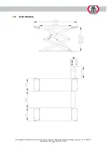
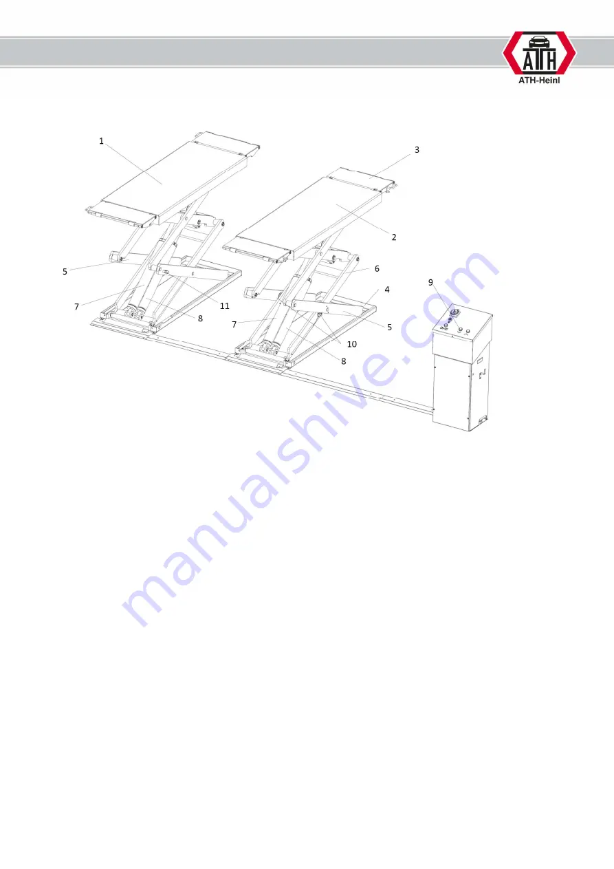
Main components
1.
Lifting platform (P1)
2.
Lifting platform (P2)
The platforms are moved upwards with internal hydraulic cylinders and the scissor principle.
The hydraulic safety device prevents the lift lowering unintentionally.
3.
Access ramp
Allows the lifting ramp to be extended
4.
Base frame
Fixing the lift
5.
Lower scissors
6.
Upper scissors
7.
Main cylinder
8.
Slave cylinder
9.
Hydraulic power unit with control box (dead-man system)
The hydraulic oil in the tank is fed to the cylinder via a gear pump driven by the
motor. A lowering valve returns the oil to the tank.
10.
CE stop & limit switch
The CE stop stops the lift descending at a height of 500 mm.
The limit switch terminates the lifting process when the maximum lifting height is reached,
protecting the hydraulic system.
11.
Light barrier
Ensures secure synchronisation of the two scissors
Summary of Contents for Frame Lift 30FZ
Page 3: ...BEDIENUNGSANLEITUNG ATH Frame Lift 30FZ ...
Page 47: ...OPERATING INSTRUCTIONS ATH Frame Lift 30FZ ...
Page 91: ...MANUEL D UTILISATION ATH Frame Lift 30FZ ...
Page 135: ...NÁVOD K OBSLUZE ATH Frame Lift 30FZ ...
Page 179: ...MANUAL DE INSTRUCCIONES ATH Frame Lift 30FZ ...
Page 223: ...BEDIENINGSHANDLEIDING ATH Frame Lift 30FZ ...
Page 267: ...INSTRUKCJA OBŁSUGI ATH Frame Lift 30FZ ...

