® Copyright ATH-Heinl GmbH & Co. KG, All rights reserved / Misprints and technical changes reserved / As of: 2020-03
Manufacturer ATH-Heinl GmbH & CO.KG
- 20 -
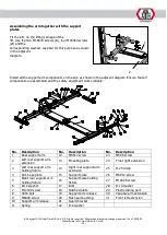
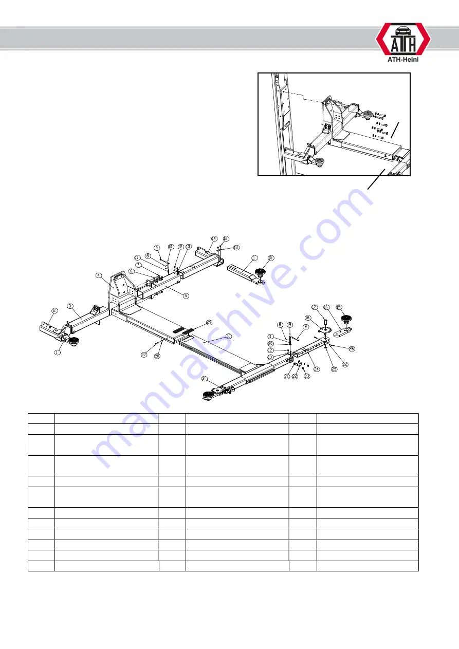
Assembling the arm together with the support
plates
Fit the arm on the lifting carriage of the
lift. Use the two M16X70 screws (
1
), four M16X60 screws
(
2
) and the
corresponding washers supplied for this purpose as shown
in the adjacent
diagram.
Install all the support arm components on the arm as shown in the adjacent diagram. Ensure that all
components are assembled and the safety equipment works reliably.
No. Description
No. Description
No. Description
1
Rear support arm
12
M8X12 screw
23
M6X8 screw
2
Left rear support arm
extension
13
Mounting plate
24
Front right extension
3
Left rear support arm
holding fixture
14
Right rear support arm
extension
25
D.25 circlip
4
Arm base plate
15
Support plate
26
M6X12 screw
5
Right rear support arm
holding fixture
16
Support plate holding
fixture
27
M10X20 screw
6
D.12 washer
17
Bolt
28
D.10 washer
7
M12X30 screw
18
Notched plate
29
Plastic sliding part
8
4X16 bolt
19
Support arm release
30
Variable arm extension
9
M8X60 screw
20
Flat-head bushing
31
Front left extension
10
Support arm release
21
Guard bracket
11
Spring
22
D.6 washer
1
2
Summary of Contents for Single Lift 35M
Page 3: ...BEDIENUNGSANLEITUNG ATH Single Lift 35M ...
Page 51: ...OPERATING INSTRUCTIONS ATH Single Lift 35M ...
Page 99: ...MANUEL D UTILISATION ATH Single Lift 35M ...
Page 147: ...NÁVOD K OBSLUZE ATH Single Lift 35M ...
Page 195: ...MANUAL DE INSTRUCCIONES ATH Single Lift 35M ...
Page 243: ...BEDIENINGSHANDLEIDING ATH Single Lift 35M ...
Page 291: ...INSTRUKCJA OBŁSUGI ATH Single Lift 35M ...


