117
6.2
Maintenance: Details
The following points deal with the most significant specific cases
6.2.1
Checking and tightening screws, bolts, plug ring nuts
The operation of the following components must be checked. If necessary, the
parts must be tightened with the appropriate tools as indicated in the charts on
the following pages.
Clamping forces and tightening torque for bolts with a normal stroke metric
thread (
use the Ma
’
torque
)
Resistance class in accordance with DIN/ISO 898
8.8
Yielding point Rp 0,2 N/mm²
640 for <= M16 / 660 for >=M16
Metric thread
ISO
Cross-section
of the
powered zone
Cross section of
the thread
Clamping
force
For hydraulic
and electrical
torque wrench
Ma
’
= 0.9
MD* for the
wrench
DIN 13
AS mm²
A3 mm²
FM [kN]
MA [Nm]
MA
’
[Nm]
M12
84.3
76.2
38.5
87
78
M14
115
105
72
140
126
M16
157
144
91
215
193
M18
193
175
117
300
270
M20
245
225
146
430
387
M22
303
282
168
580
522
M24
353
324
221
740
666
M27
459
427
270
1100
990
M33
561
519
335
1500
1350
M36
694
647
395
Bolt determined by measuring
the yielding
M39
817
759
475
M42
976
913
542
Summary of Contents for 1090 EVO
Page 7: ...7...
Page 22: ...22...
Page 23: ...23...
Page 49: ...49 37 Combustion engine 38 Fuel tank 39 Bi levelling chassis 37 38...
Page 78: ...78...
Page 80: ...80...
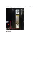
Page 122: ...122 In this configuration the oil level must be as shown in the figure below A 60mm...
Page 144: ...144...
Page 145: ...145...
Page 146: ...146...
Page 147: ...147...
Page 148: ...148...
Page 149: ...149...
Page 150: ...150...
Page 151: ...151...
Page 152: ...152...
Page 161: ...161 8 ATTACHMENTS 8 1 Declaration of conformity...
Page 163: ...163 MANDATORY ROUTINE INSPECTIONS Date Observations Seal Signature...
Page 177: ...177 8 4 Hydraulic diagram See attachment 8 5 Wiring diagram See attachment...


