125
Checking the maximum pressure valves relating to lifting (2)
The pressure gauge relating to this valve is the one connected to outlet 4.
d)
Start the internal combustion engine.
e)
Press the platform "up" button (
15
) until it reaches the limit and hold it
down. This activates the pressure relief valve of the lift circuit.
f)
Read the pressure on the gauge, which should be 160 bar ± 5 bar
Warning: to allow the lifting cylinder to reach its mechanical limit switch, it is
necessary to disable the electronic limit switch. Only specialised technicians,
authorised by Almac Srl, must perform this operation.
The valves are calibrated during the testing phase performed by ALMAC Srl and
should not require further adjustment unless:
•
the hydraulic circuit is replaced
•
the actual pressure relief valve is replaced
In these cases, the valve must be calibrated by SPECIALIZED PERSONNEL
according to the monitoring procedure described above. Using the appropriate
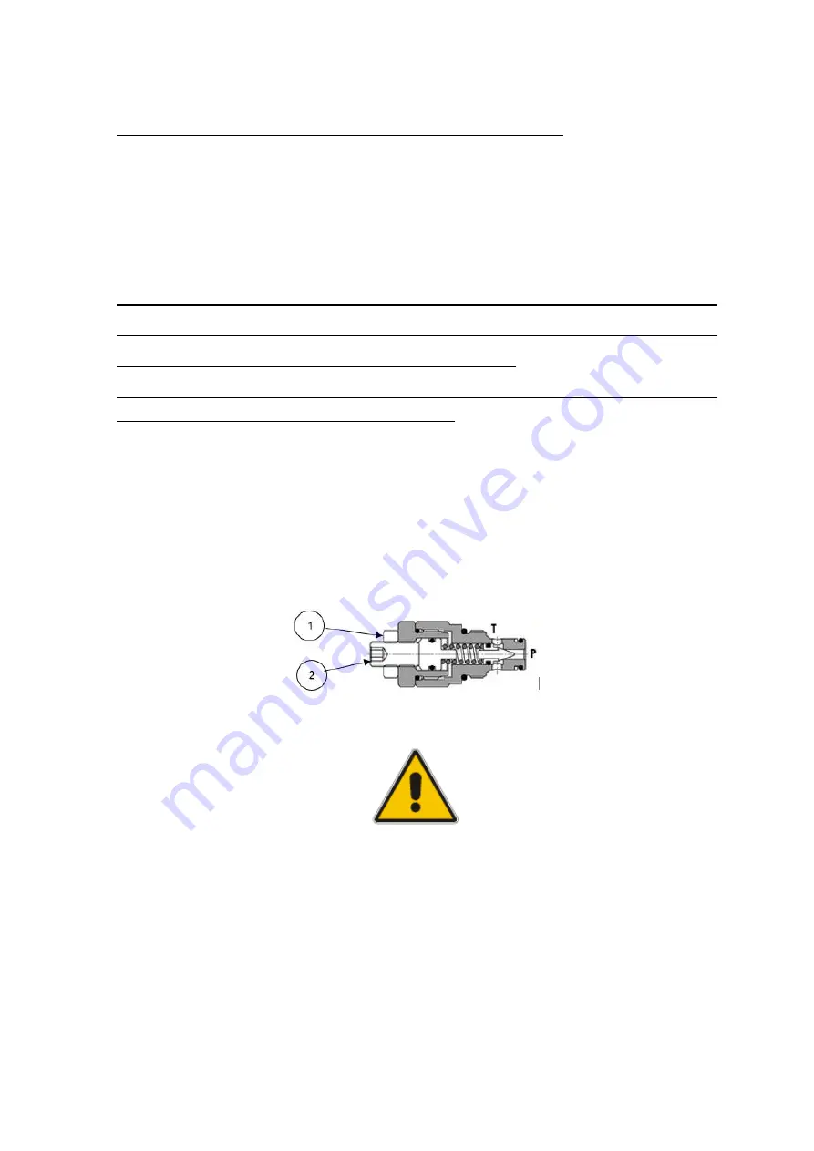
tools, unscrew the lock nut (1) and tighten or loosen the adjuster screw (2) until
the indicated pressure level has been reached. Once the adjustments have
terminated, tighten the lock nut (1) to hold the screw in position.
Diagram of the pressure relief valve
Warning: the calibration operation must only be performed by SPECIALIZED
personnel. It must not be done by a generic operator.
6.2.9
Battery
6.2.9.1
General warnings
The battery is an essential component for machine operation. It is important to
ensure that it remains in a good condition over time since this will lengthen its
Summary of Contents for 1090 EVO
Page 7: ...7...
Page 22: ...22...
Page 23: ...23...
Page 49: ...49 37 Combustion engine 38 Fuel tank 39 Bi levelling chassis 37 38...
Page 78: ...78...
Page 80: ...80...
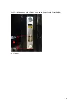
Page 122: ...122 In this configuration the oil level must be as shown in the figure below A 60mm...
Page 144: ...144...
Page 145: ...145...
Page 146: ...146...
Page 147: ...147...
Page 148: ...148...
Page 149: ...149...
Page 150: ...150...
Page 151: ...151...
Page 152: ...152...
Page 161: ...161 8 ATTACHMENTS 8 1 Declaration of conformity...
Page 163: ...163 MANDATORY ROUTINE INSPECTIONS Date Observations Seal Signature...
Page 177: ...177 8 4 Hydraulic diagram See attachment 8 5 Wiring diagram See attachment...


