35
2.9
Mandatory safety indications to follow before lifting the work
platform above the transport height
The instructions given below must be followed.
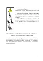
After having levelled it, lift the work platform only after making sure, both
visually and by moving inside the work platform, that all 4 ends of the tracks
rest on the ground.
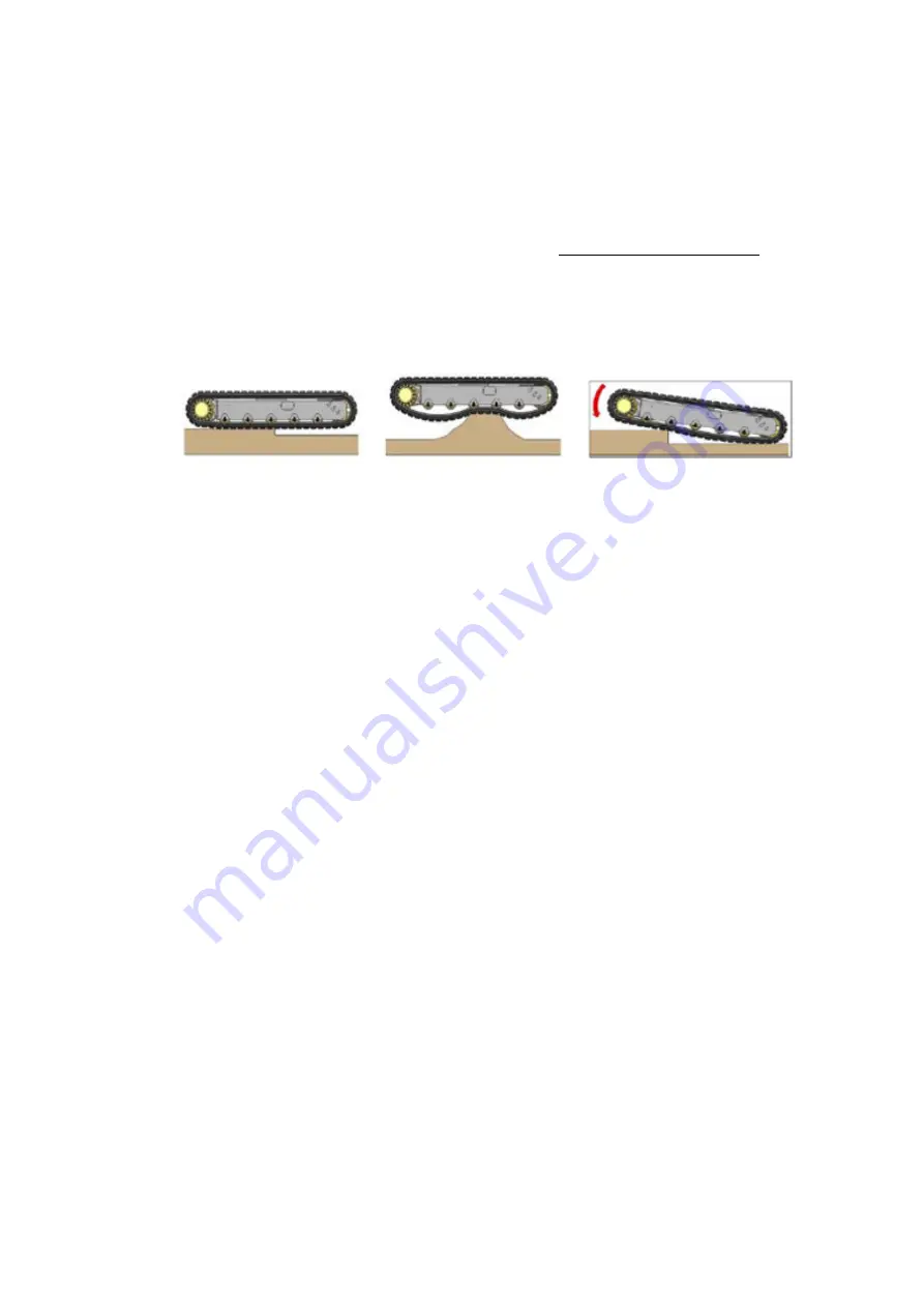
Avoid the following situation for both tracks:
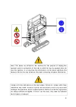
The ring gear of the wheel drive units and the track tensioner wheels must all be
resting on the ground.
If even one of them is not in contact with the ground, the stabiliser area will be
reduced and, consequently, the platform will be unstable and there will be the
risk of overturning.
2.10
Safety checks on the operation of the platform, to be performed
before use
The instructions given below must be followed.
•
With the platform in the transport configuration, place the machine with the
frame tilted with respect to the horizontal by a value greater than 0.5° on
the lateral. Operate the platform lifting control, make sure that the system
automatically brings the frame to the horizontal position
•
With the platform in the transport configuration, place the machine with the
frame tilted with respect to the horizontal by a value greater than 0.5° on
the longitudinal. Operate the platform lifting control, make sure that the
system automatically brings the frame to the horizontal position
•
With the platform in the transport configuration, place the machine with the
frame tilted with respect to the horizontal at the maximum angle both on
the longitudinal and on the lateral. Operate the platform lifting control,
make sure that the system automatically brings the frame to the horizontal
position
•
Lift the platform without a load to the maximum height and then lower it a
few times; make sure that the machine works correctly
Summary of Contents for 1090 EVO
Page 7: ...7...
Page 22: ...22...
Page 23: ...23...
Page 49: ...49 37 Combustion engine 38 Fuel tank 39 Bi levelling chassis 37 38...
Page 78: ...78...
Page 80: ...80...
Page 122: ...122 In this configuration the oil level must be as shown in the figure below A 60mm...
Page 144: ...144...
Page 145: ...145...
Page 146: ...146...
Page 147: ...147...
Page 148: ...148...
Page 149: ...149...
Page 150: ...150...
Page 151: ...151...
Page 152: ...152...
Page 161: ...161 8 ATTACHMENTS 8 1 Declaration of conformity...
Page 163: ...163 MANDATORY ROUTINE INSPECTIONS Date Observations Seal Signature...
Page 177: ...177 8 4 Hydraulic diagram See attachment 8 5 Wiring diagram See attachment...

