112
KEY
A.
Whenever the machine is
used
D. monthly or every 100 hours G. annually or every 1500 hours
B.
Daily or every 10 hours
E. every two months or every
250 hours
H. after long periods of inactivity (30 days)
C.
Weekly or every 50 hours
F. quarterly or every 500
hours
* Refer to the engine use and maintenance
manual
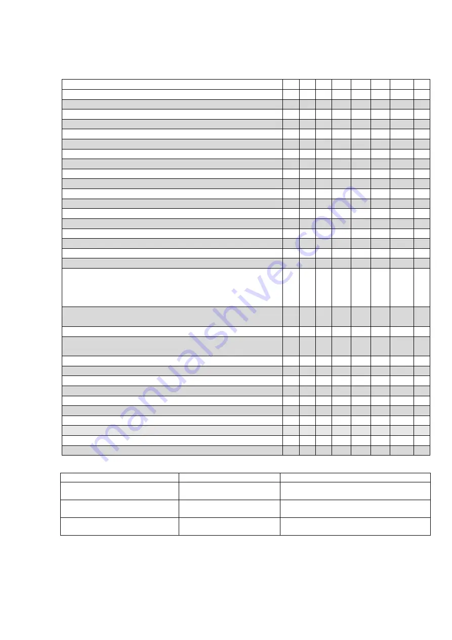
ORDINARY MAINTENANCE SCHEDULE TABLE
A
B
C
D
E
F
G
H
10 50 100 250 500 1500
Visual and functional checks as specified
X
X
Discharge filter cartridge replacement
X
X
Suction filters replacement
X
X
Check and, if necessary, grease the runners and nylon wheels
X
X
X
Check the hydraulic oil level
X
X
Change the hydraulic oil
X
Track reduction gear oil level inspection
X
X
Replace oil in the track reduction gear
X
Check the oil level in the engine
X
X
Change the engine oil * (after the first 20 hours)
X
Replace engine oil filter.*
X
X
Clean the engine air filter.*
X
X
Replace engine air filter.*
X
Track inspection and tensioning
X
X
Check the condition of the tracks
X
X
Check the runners for wear
X
Check the tightening of nuts and bolts (general checks)
X
Check using a torque wrench the tightening of screws and bolts
for fixing of the tracked chassis to the machine frame, the
screws M16 class8.8 tightening torque 193 Nm (after the first
50 hours)
X
Check the correct positioning of the Seeger rings of the
scissors and their washers
X
X
Structural inspection (visual)
X
X
X
Structural inspection (through checking of metal parts and
welds)
X
X
Check the overload monitoring device
X
Manual emergency devices
X
X
Check the combustion engine battery
X
X
Check the correct operation of the 230V outlet differential
X
X
Check the Proactive levelling angle sensor
X
Check the Proactive levelling redundancy valves
X
Check and replace the fuses
X
X
Check the maximum pressure valve
X
Check the main system angle sensors
X
X
Check the correct operation of the Sentinel
X
Summary of Contents for 1090 EVO
Page 7: ...7...
Page 22: ...22...
Page 23: ...23...
Page 49: ...49 37 Combustion engine 38 Fuel tank 39 Bi levelling chassis 37 38...
Page 78: ...78...
Page 80: ...80...
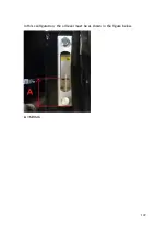
Page 122: ...122 In this configuration the oil level must be as shown in the figure below A 60mm...
Page 144: ...144...
Page 145: ...145...
Page 146: ...146...
Page 147: ...147...
Page 148: ...148...
Page 149: ...149...
Page 150: ...150...
Page 151: ...151...
Page 152: ...152...
Page 161: ...161 8 ATTACHMENTS 8 1 Declaration of conformity...
Page 163: ...163 MANDATORY ROUTINE INSPECTIONS Date Observations Seal Signature...
Page 177: ...177 8 4 Hydraulic diagram See attachment 8 5 Wiring diagram See attachment...


